4
AEROFOIL
• An aerofoilis a streamlined
body that can generate
significantly more lift than
drag.
• Examples of aerofoils
include:
oAirplane wings
oPropeller blades
oHelicopter rotor blades
oSails
oWind turbine blades
10
BOUNDARY LAYER CONTROL
•Boundary layer control The techniques that have been developed to
manipulate the boundary layer either to increase lift or decrease drag.
Boundary
layer control
Transition Separation
11.
11
CONTROLLING TRANSITION
BY SHAPINGTHE AEROFOIL
Transition
point
25% of
cord
50%
Max thickness
Adverse P.G.
Adverse pressure gradient promotes instabilities and expedites (hasten) laminar-
turbulent transition
12.
13
CONTROLLING TRANSITION
BY SUCTION
Transitionpoint
Delays transition to turbulence
(Reduces friction drag)
Weakens instabilities
Reduces velocity gradient
Removes the low-momentum fluid next to the surface
Suction
13.
14
CONTROLLING SEPARATION
BY SUCTION
Inturbulent flow
Suction removes low-momentum flow
near the wall
Draws higher-energy air closer to the
surface
Increases the flow momentum near the
surface
Allow BL to resist separation
14.
15
BY BLOWING JET
Theblowing jet helps to overcome the adverse pressure gradient that causes
separation
Blowing jet
15.
16
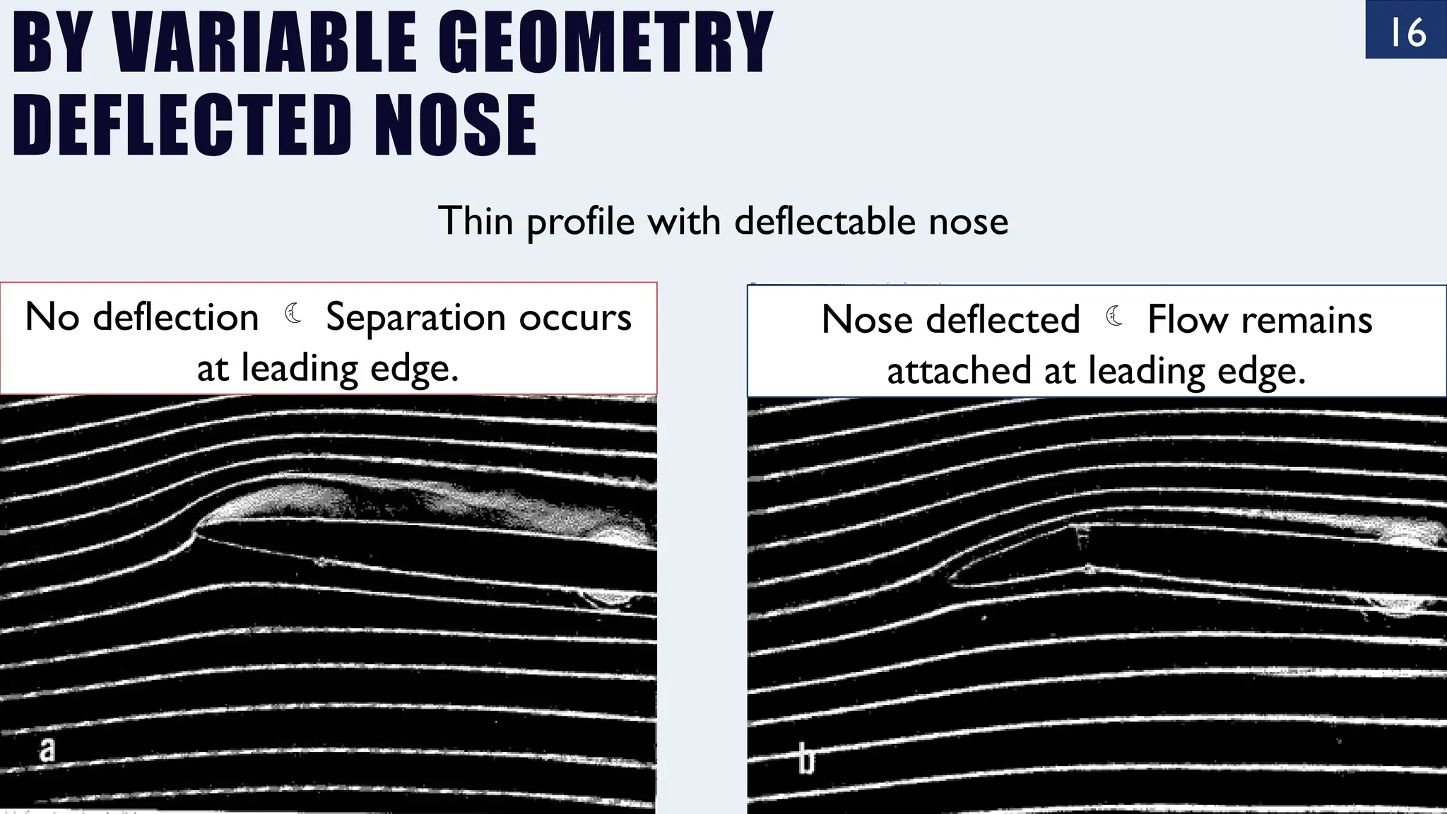
BY VARIABLE GEOMETRY
DEFLECTEDNOSE
Thin profile with deflectable nose
No deflection Separation occurs
at leading edge.
Nose deflected Flow remains
attached at leading edge.
16.
17
BY VARIABLE GEOMETRY
VORTEXGENERATORS
Vortex generators can delay separation
by mixing high-momentum fluid from
the outer flow with low-momentum
fluid next to the airfoil surface.
17.
18
FLAPS
• Flaps arehinged or retractable surfaces
on the trailing edge of an aircraft's wing
that increase lift and drag when
deployed.
20
BY VARIABLE GEOMETRY:SLOTS
• Blowing jets are created
naturally.
•A leading-edge slot leads
air from near the stagnation
point through a converging
channel and ejects it at high
speed at the low-pressure
region on the upper surface.
•Flap (trailing-edge) slots
Leading-edge slot Trailing-edge slotted flap
26
#2
FRONT SPLITTER
• Thefront splitter helps improve stability and cornering by increasing
downforce at the front of the vehicle.
26.
27
#3
DIVE PLANES
• Diveplanes deflect the wind upwards, pushing the front of the car down as a
result. which improves grip and stability, especially during cornering.
27.
28
#4
WHEEL ARCH VENTILATION
•The front wheels rotate at a high velocity which creates a high-pressure zone
inside the wheel well.
D ↓
L ↓
Brake cooling
28.
29
#5
TOP AIR INTAKE
1.Fills the engine with undisturbed, high-speed, denser airstream.
2. Regulates engine temperatures.
3. Minimizes drag while optimizing airflow.
34
• A caris said to oversteer when the rear wheels do not track behind the front
wheels but slide out towards the outside of the turn.
• Understeer is the condition in which the front tires do not so follow the
intended trajectory the driver is trying to impose while taking the corner,
34.
36
SUMMARY
• Lift anddrag concepts
• Drag
–Friction drag
–Pressure drag
–Shape dependence
–Reynolds number dependence
–Surface roughness dependence
–Composite body drag
• Lift
–Aerofoil aerodynamics
–Boundary layer control
–Racing car aerodynamics
#10 Transition of the laminar layer to a turbulent layer
Separation of the entire flow from the surface
#11 The right airfoil has a minimum pressure point farther aft, and the extent of adverse gradient is therefore less. Flow studies show that the extent of the laminar boundary layer is correspondingly increased.
#12 A rather different means of stabilizing the boundary layer is the use of suction. Suction may be applied either through porous surfaces or through a series of finite slots, as in Fig. 8. When applied in this manner, suction reduces the thickness of the boundary layer by
removing the low-momentum fluid next to the surface. This reduces the velocity gradients near the wall. This reduction in velocity gradient weakens instabilities that would otherwise amplify and lead to turbulence.
A more stable layer results, and transition to turbulence is delayed.
To achieve stabilization of the boundary layer at various angles of attack, compromises must be made as to the number of slots, their location, and the amount of suction flow through each slot.
A wake survey (Fig. 9) shows that, even with such compromises, suction can be effective. Without suction the wake is broad, indicating high drag. The application of suction greatly reduces the streamwise momentum loss in the wake. If the suction is applied only on one surface, as in the case demonstrated, the wake reduction will not be symmetrical (cf. Fig. 7). Power is needed to achieve this drag reduction. The optimum condition occurs when the total drag - the aerodynamic drag plus the suction power converted to an equivalent drag is a minimum.
#13 A rather different means of stabilizing the boundary layer is the use of suction. Suction may be applied either through porous surfaces or through a series of finite slots, as in Fig. 8. When applied in this manner, suction reduces the thickness of the boundary layer by
removing the low-momentum fluid next to the surface. This reduces the velocity gradients near the wall. This reduction in velocity gradient weakens instabilities that would otherwise amplify and lead to turbulence. A more stable layer results, and transition to turbulence is delayed.
To achieve stabilization of the boundary layer at various angles of attack, compromises must be made as to the number of slots, their location, and the amount of suction flow through each slot.
A wake survey (Fig. 9) shows that, even with such compromises, suction can be effective. Without suction the wake is broad, indicating high drag. The application of suction greatly reduces the streamwise momentum loss in the wake. If the suction is applied only on one surface, as in the case demonstrated, the wake reduction will not be symmetrical (cf. Fig. 7). Power is needed to achieve this drag reduction. The optimum condition occurs when the total drag - the aerodynamic drag plus the suction power converted to an equivalent drag is a minimum.
#14 There are many cases in which control of boundary-layer separation is important. Suction can be used for this purpose, too. If a profile equipped with suction slots is placed at a high enough angle of attack (Fig. 10a), suction will not be able to maintain the entire boundary layer in the laminar state. It can, however, exert a profound effect upon the turbulent layer, frequently keeping the flow attached well beyond the angle at which stalling occurs without suction (Fig. 10b). In general, more suction power is required to attach a flow that is already stalled than to maintain attached flow at the same angle of attack.
Separation control by suction is accomplished by drawing the low-momentum layers from the bottom of the boundary layer into the suction slots. This draws the higher-energy air from the outer layers closer to the surface.
#17 On both aircraft and wind turbine blades they are usually installed quite close to the leading edge of the aerofoil in order to maintain steady airflow over the control surfaces at the trailing edge
Vortex generators are often arranged in pairs (counter-rotating pairs, specifically) because this configuration creates a stable, balanced vortex pattern that enhances the effectiveness of the generated vortices. Here’s why pairs are beneficial:
1. Counter-Rotating Vortices for Stability
A pair of vortex generators creates two counter-rotating vortices, which stabilize each other as they travel downstream. This mutual stabilization prevents the vortices from quickly dissipating or merging, allowing the mixed high-energy air to persist over a longer distance. As a result, the boundary layer stays energized and attached to the surface for a longer distance, reducing drag and separation more effectively.
2. Enhanced Mixing and Momentum Transfer
Counter-rotating vortex pairs increase the level of mixing between the faster-moving air in the outer flow and the slower air in the boundary layer. This cross-stream mixing is more intense and uniform, which boosts the overall energy within the boundary layer, making it more resistant to separation.
3. Reduced Asymmetrical Effects
Using single vortex generators could create an uneven or asymmetrical flow, which may lead to localised, uneven drag or lift. Pairs help in maintaining symmetry across the surface and in distributing the aerodynamic effects uniformly, which is particularly important in applications like aircraft wings or turbine blades where consistent flow is needed.
4. Practical Efficiency
Arranging vortex generators in pairs allows engineers to achieve the desired boundary layer control with fewer generators, conserving space and reducing weight, which is especially important in aerospace and automotive applications. Fewer, more effective pairs can create the same drag-reduction effects as a larger array of single generators, improving overall efficiency.
#18 The flaps do not mitigate separation, but they slots within the flaps can do.
#19 Landing comes from deceleration by drag not by reducing lift directly
#20 Blowing jets directed into critical areas are useful.
These can be created by utilizing the pressure differences that exist on the aerodynamic bodies themselves.
A leading-edge slot is an example. When open it leads air from the region close to the stagnation point through a converging channel and ejects it at high speed at a point of low pressure on the upper surface.
The same concept is used to decrease the extent of separation on deflected flaps. Fluid is led from the high-pressure region below the flap through a converging channel and ejected over the upper surface close to the point of minimum pressure. This helps to overcome the strong adverse pressure gradient existing on the upper surface of the flap. Multiple-slot arrangements though more complicated have proven to be particularly effective.
#21 Types of Flaps
1. Plain Flaps
They extend from the trailing edge of the wing and pivot downward when deployed, increasing the wing’s camber.
While plain flaps do a fine job of increasing lift, they also produce significant drag.
This drag isn’t always a bad thing, especially when you’re trying to reduce speed for landing.
But during takeoff, it could make your aircraft work harder to get into the air.
A favorite for smaller, less complex aircraft. Their simplicity also means less maintenance, which is music to any pilot’s ears.
2. Split Flaps
They’re attached to the underside of the wing, and when deployed, they drop down from the wing’s trailing edge. This action increases the wing’s lift.
It creates an abrupt, high-drag airfoil shape, enhancing lift generation but also producing significant drag.
They’re commonly seen on vintage or older aircraft, while not as prevalent in newer models.
3. Slotted Flaps
Have one or more slots or gaps that allow high-pressure air from the underside of the wing to pass through to the top when the flaps are extended.
This nifty feature delays the airflow separation that leads to stall, allowing for a higher angle of attack and hence more lift, all without creating excessive drag.
They’re a common feature on many types of aircraft, from small general aviation planes to larger commercial jets, thanks to their efficient lift-to-drag ratio.
4. Fowler Flaps
Fowler flaps are a favorite among many pilots, especially those flying high-performance aircraft.
When deployed, these flaps slide backward on tracks or rails before hinging downwards. This action not only increases the wing’s camber, but it also extends the wing’s surface area.
This increase in surface area, coupled with a more pronounced camber, leads to a significant lift increase.
The rearward movement of Fowler flaps also creates a slot, similar to slotted flaps. This slot allows for smoother airflow and higher lift generation at steeper angles of attack, without an excessive drag penalty.
Fowler flaps truly are the masters of lift and control, which is why you’ll often find them on larger, faster aircraft.
5. Slotted Fowler Flaps
Think of these as the best of both the slotted and Fowler worlds.
They bring together the increased wing area and lift of Fowler flaps with the smooth, efficient airflow of slotted flaps.
Slotted Fowler flaps slide backward and then hinge downwards when deployed, much like standard Fowler flaps. The magic happens in the series of slots created in this process, which enable high-pressure air from beneath the wing to move to the top. This results in better lift and stall characteristics, particularly beneficial at low speeds during takeoff and landing.
Preventing it from stalling at higher angles of attack.
Due to their intricate design and superior performance, slotted Fowler flaps are often found on larger, commercial aircraft.
#22 Multiple-slot arrangements though more complicated have proven to be particularly effective.
#26 When oncoming air hits the car, a high-pressure zone is generated in front of the bumper. This high pressure pushes onto the front bumper as well as down onto the splitter. The resulting pressure difference between the top surface of the splitter and the fast, low-pressure air passing below, creates a net force that sucks the splitter towards the ground - generating downforce for the front tires.
The resulting downforce pushes the front of the car toward the road, enhancing traction on the front wheels, especially during high-speed turns. This increased grip allows the car to corner more effectively and reduces the risk of understeer. Additionally, splitters often work with other aerodynamic elements like diffusers and rear wings to balance downforce across the car, further improving stability at high speeds.
#28 Wheel arch ventilation in race cars serves to improve aerodynamics, cooling, and brake performance by managing the turbulent airflow generated around the wheels.
When air flows through and around the rotating wheels, it creates high-pressure zones within the wheel wells. This turbulent, trapped air increases drag and can lift the front of the car slightly, reducing downforce.
Wheel arch vents allow this trapped, high-pressure air to escape from the wheel wells, decreasing drag and improving downforce. In some cases, this ventilation also helps cool the brakes by allowing hot air to dissipate from the brake assemblies, enhancing braking performance and extending brake life, especially under high-stress racing conditions. The improved airflow around the wheels contributes to overall stability and better aerodynamic efficiency at high speeds.
#29 The top air intake on a race car serves to direct fresh, high-pressure air into the engine's intake manifold.
Positioned above the car's cabin or cockpit, the intake benefits from an undisturbed, high-speed airstream, allowing it to "ram" cooler, denser air into the engine. This helps increase the amount of oxygen available for combustion, resulting in a boost in engine power and efficiency.
The top air intake also plays a role in cooling. By channeling air into the engine bay, it helps regulate engine temperatures, preventing overheating during prolonged high-performance runs.
Its location and design are chosen to minimize drag while optimizing airflow.
#30 Rear wings perform optimally when placed in clean airflow, free from the turbulence and energy loss generated by other upstream components.
Rear wings on race cars are vital aerodynamic elements designed to create downforce at the back of the vehicle. By forcing air up and over the wing's surface, they generate a pressure differential: high pressure above the wing and lower pressure below. This downforce pushes the rear wheels onto the track, improving traction and stability, especially at high speeds.
The increased downforce from the rear wing helps prevent oversteer, where the rear tires lose grip in a turn. This stability allows drivers to take corners at higher speeds and gives them more control under braking. The angle of the rear wing, called the angle of attack, can often be adjusted to balance between downforce and drag, allowing race engineers to fine-tune the car’s performance based on track conditions. A steeper angle generates more downforce but also increases drag, which can slightly reduce top speed, while a lower angle reduces drag, benefiting straight-line speed at the expense of cornering grip.
#33 Increases the flow underneath the car (single pipe vs two pipes in series one is larger)
A diffuser is the section of the rear underfloor which has been shaped with an upward angle. As air travels underneath the car, it then expands through this diffuser section. Here, the Venturi effect takes place. As air is expanded from a narrow cross section to a wider cross section, air velocity decreases and pressure increases. Therefore, the air under the car has high velocity and low pressure. As this air moves through the expansion chamber, created by the diffuser, the velocity then decreases which results in an increase in pressure. Once again, this difference in pressure helps to draw the air out from underneath the car, creating more downforce.
The shape of the diffuser also improves the transition of air from underneath the car to the surrounding air as well as fill the wake.
A strong aerodynamics package not only generates high downforce and low drag, but also maintains a consistent ratio of front to rear downforce. This is known as aerodynamic balance and controlling this balance ensures that all four tires on the race car work equally hard. An imbalance of tire forces can lead to understeer or oversteer which ultimately sacrifices lap time. Therefore, it's important to understand the performance of the entire aerodynamic package and how one device affects another downstream when developing aerodynamic components. Learn more about aero mapping.