High Density WLAN
Ben van Zeggelaar
Aruba Customer Engineering (ACE)
CONFIDENTIAL
© Copyright 2012. Aruba Networks, Inc.
All rights reserved
2
Aruba Validated Reference Designs
– Aruba is the thought leader in our industry.
We produce a library of Validated
Reference Designs
– The Very High Density (VHD) WLANs VRD
covers ultra high capacity spaces such as
auditoriums, arenas, stadiums and
convention centers
– The recommendations have been field
proven at dozens of customers
– VRDs are free to download from Aruba
Design Guides web page:
http://www.arubanetworks.com/VRD
3
HD WLANs are Challenging, but…
– Uncontrolled mix of device types, OS, driver levels, and radio types
– Multiple devices per person – up to three
– Per-user bandwidth needs can easily exceed what is allowed by Wi-Fi and physics
– Simultaneous data plane spikes during events
– Inrush/outrush demand increases load on network control plane, address space, etc.
– Most devices limited to 1x1:1 HT20 operation
– Other Issues:
– Customer traffic need to be segregated from operational and other vendor traffic
– Wi-Fi networks need to be optimized to support video and other high bandwidth / latency sensitive
applications
4
Agenda
– Channel capacity
– Interference radius
– Coverage strategies
– Best Practices
5
What exactly is “(Very) High Density”
– Many users
– Many users need WiFi connectivity and speed
– Many different device types
– Multiple APs are needed to associate the WiFi devices
– Use many channels to provide the bandwidth
– Many APs
– More APs then available channels.
– Re-use of channels = Introducing co-channel interference
Key characteristic of a HD Wireless LAN is that there we need more APs than available channels in
the area to cover where distances between APs is much smaller than the interference radius.
6
Many users - Understanding Association Capacity
– Association capacity means the number of devices that the HD WiFi network can “carry”.
– To add association capacity, all we have to do is add APs
=
=
7
Many APs - Understanding Transmit Capacity
– Transmit capacity is the number of lanes on the road - (or out of the parking lot
after the game)!
2.4GHz 5GHz
1 6 11
36 40 44 48 149 153 157 161 165
8
WiFi Channel
– WiFi Channel capacity is limited
– The fact that an AP can do 600Mb/s doesn’t mean the
users will get 600Mb/s
– WiFi channel is shared between the devices on
the channel (not just the AP radio!)
– Phy rate depends on Signal to Noise Ratio (SNR)
– Typical Noise floor for 5Ghz:: -95dB
– Typical Noise floor fro 2.4Ghz: -90dB
– This depends on the environment and increases due
to ACI!!
– The Transmission rate determines the airtime
taken by a device/AP for sending a frame.
– The higher transmission rate, the quicker the
device/AP is “of the air”.
– Client bandwidth is dependent PHY/Transmission
rate and is half duplex
– Expected TCP Throughput (what you get with
ADSL Speedtest) is roughly half the PHY rate in
HD-WLAN as it includes channel impairment
(interference, channel contention etc.)
9
Measured 20MHz Channel Capacity – 11n
802.11n 5-GHz Aggregate Mixed-Mode TCP Client Scaling Performance
(AP-225, HT20, TCP Bidirectional)
10
Measured 20MHz Channel Capacity – 11ac
10
802.11n 5-GHz Aggregate Mixed-Mode TCP Client Scaling Performance
(AP-225, VHT20, TCP Bidirectional)
11
Approaching the Limit of Wi-Fi Performance
Below 50 concurrent users per radio,
AP count and self-interference grows
dramatically
User experience is unacceptable
beyond 50 concurrent users per radio
12
Approaching the Limit of Wi-Fi Performance – Why?
12
Breakdown of 802.11 Control Frame Types (AP-225, 20-
MHz Channel, TCP Up)
Read the VHD VRF Theory guide for a good explanation on PHY rates vs client throughput
13
Available Channel Count
– Channel bonding (HT40) reduces
capacity in HD WLANs
– 20MHz channels should be used in
2.4 and 5 GHz bands
– Available channel count varies
from country to country.
– Europe Channel Count is limited to 4
without DFS
– This limitation requires
sophisticated engineering in LPV’s
to re-use channels as many time
as possible
– The goal is to use structural
components to isolate pico-cells
14
Determining Total Capacity – No Reuse
15
I need more APs than channels available. Now what?
– In VHD WLANs we have to use channels more than once
– Reusing a channel doesn’t necessarily increases bandwidth as APs on the same channel can hear each
other.
– Also a client transmitting on a channel is heard by all APs on that channel.
– Only when it is possible to “re-use the spectrum” we add bandwidth.
15
-30dB
Reuse factor =1
Reuse factor = 2
16
How CCI Reduces WLAN Performance
–Any Wi-Fi device detecting an 802.11 frame on the air cannot transmit/ receive until the
frame has ended.
–If the transmit/receive stations are on the same channel and can decode one another's
frames, it is the case.
17
Interference Radius
– Cell Edge Radius(r1)
– This is what we usually call the “cell edge” of the AP
– It is the target data rate radius (e.g. -67dBm = MCS15 or 54Mbps)
– Interference Radius (r2)
– 802.11 preamble can be decoded (SNR >= 4dB)
-65dBm
25 SNR
r 2r 4r 8r
-71dBm
19 SNR
-77dBm
13 SNR
-83dBm
7 SNR
20m 40m 80m 160m
Preamble
Continues
to
4 SNR
and
>250m !!!!
18
How to control the “cell-size”
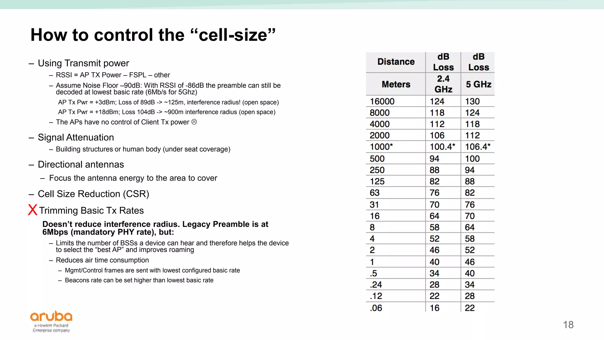
– Using Transmit power
– RSSI = AP TX Power – FSPL – other
– Assume Noise Floor –90dB: With RSSI of -86dB the preamble can still be
decoded at lowest basic rate (6Mb/s for 5Ghz)
AP Tx Pwr = +3dBm; Loss of 89dB -> ~125m, interference radius! (open space)
AP Tx Pwr = +18dBm; Loss 104dB -> ~900m interference radius (open space)
– The APs have no control of Client Tx power 
– Signal Attenuation
– Building structures or human body (under seat coverage)
– Directional antennas
– Focus the antenna energy to the area to cover
– Cell Size Reduction (CSR)
Trimming Basic Tx Rates
Doesn’t reduce interference radius. Legacy Preamble is at
6Mbps (mandatory PHY rate), but:
– Limits the number of BSSs a device can hear and therefore helps the device
to select the “best AP” and improves roaming
– Reduces air time consumption
– Mgmt/Control frames are sent with lowest configured basic rate
– Beacons rate can be set higher than lowest basic rate
X
19
Cell Size Reduction
– Adjusting AP receive sensitivity with Cell Size Reduction (CSR), helps the APs to automatically reject
interference from co-channel sources outside the high-density coverage area
– CSR can also provide some immunity to ACI sources within the same auditorium or high-density
environment
Read the Very High-Density VRD for more
details. Configuring CSR can be dangerous!!
20
Cell size – Client Tx vs AP Tx
– Once you have carefully created you “cells”, you still
have to deal with CCI caused by client devices
– Enabling TPC, 802.11h/k has mechanisms to control
Client Transmit Power , but it is not or poorly
implemented by clients,
– Recommend to enable 802.11h/k (default disabled)
21
Coverage Strategies for HD Areas
Overhead coverage is a good choice
when uniform signal is desired
everywhere in the target area
Under-seat or on-floor mounting –
also known as a “picocell” design –
uses very small cells to maximize
reuse.
Wall installations are most often seen
where ceiling or under-floor access is
not possible or too expensive.
22
Extend Uniformity to Adjacent HD WLANs
23
Factors that influence coverage strategy
– RF propagation
– Distance between client and AP.
– Distance between APs
– Signal obstructions
– Esthetics
– Mainly indoor venues with nice and/or acoustic wall finishing
– Mounting constraints
– You can’t always mount where you think you can mount. E.g in exhibition halls where
minimal height need to be respected.
– Presence of 3G/4G Antennas
– Max cable length
– AP/Antenna tampering.
– I.e certain stadiums refuse under-seat solutions
– Lifts, Rigging etc.
– Maintenance
23
24
Example Pico Cell Installation
25
AP in a water and shock resistant box
25
Preferred AP model:
AP-228 with AP-
ANT-32
26
Example Pico Cell installation (Indoor)
4 x AP-ANT -12B
27
Example Wall-Mount
28
Example Ceiling Mount
28
Mount Height h < 8m 8< h >12 h >12m
AP Integrated
Antenna
60 degree sector 30 degree sector
AP AP-335 AP-334 AP-228 or AP-274
Antenna example n/a AP-ANT-48 (dual-band) AP-ANT-2314 (2.4Ghz)
AP-ANT-5314 (5Ghz)
29
AP-ANT-5314 Foot print
– Each box represents 10x10m
29
25M
30
VHD WLAN – Not just about APs and controllers
– Recommend using a single flat VLAN (e.g. /17)
– (Core)switch should be able to handle many MAC address
– Router/firewall needs to support large ARP cache
– Local high performance DNS and DHCP server
– High performance Captive portal
– External captive portal server
– Sufficient Controller capacity to handle redirections
– Uplink capacity
– NAT
30
31
HD WLAN – Best Practices
– Read the VHD-VRD Engineering guide
– In Summary
– 1 AP per 150 Associations or 1 AP per 80-100 seats when using under-seat deployment
– Design for 5Ghz band. 2.4Ghz will be best effort only. Depending on coverage disable certain 2.4Ghz radios
– Static channel assignment for 2.4Ghz, unless AOS8 Airmatch (requires MM).
– Fix channel assignment to avoid unnecessary channel changes (arm assignment=‘maintain’)
– Look for true radar events (show log wireless all | include Radar) and disable channel if needed
– Limit number of SSIDs in the HD areas
– Ideally just 1 Open SSID, or 2 SSIDs (one open and one dot1x)
– Use Radius to separate users on the secure SSID (i.e employees, ticket-sales/scanners, POS)-
– Always configure MAC-caching in combination with Captive Portal
– Set the right expectations!
– WiFi has its limits, but if designed correctly, it works
– Don’t promise anything on 2.4Ghz
31
32
HD WLAN – Best Practices
– Every 𝛍s airtime counts
– Set local probe threshold (6<LPTR<10) (LPTR 3dB less than cm-sticky-snr)
– Configure ‘broadcast-filter all’
– Use lowest Tx Power possible. Target -68dB at client. Pico-cell uses relatively high power settings
– Trim TX rates >24Mbps
– Deny inter-user bridging
– Use CSR carefully. Start with low value (e.g 6)
– Turn of 802.11b protection
– Use always DMO for multicast video streaming
32
Thank You
Questions?

Airheads Meetups- High density WLAN

  • 1.
    High Density WLAN Benvan Zeggelaar Aruba Customer Engineering (ACE) CONFIDENTIAL © Copyright 2012. Aruba Networks, Inc. All rights reserved
  • 2.
    2 Aruba Validated ReferenceDesigns – Aruba is the thought leader in our industry. We produce a library of Validated Reference Designs – The Very High Density (VHD) WLANs VRD covers ultra high capacity spaces such as auditoriums, arenas, stadiums and convention centers – The recommendations have been field proven at dozens of customers – VRDs are free to download from Aruba Design Guides web page: http://www.arubanetworks.com/VRD
  • 3.
    3 HD WLANs areChallenging, but… – Uncontrolled mix of device types, OS, driver levels, and radio types – Multiple devices per person – up to three – Per-user bandwidth needs can easily exceed what is allowed by Wi-Fi and physics – Simultaneous data plane spikes during events – Inrush/outrush demand increases load on network control plane, address space, etc. – Most devices limited to 1x1:1 HT20 operation – Other Issues: – Customer traffic need to be segregated from operational and other vendor traffic – Wi-Fi networks need to be optimized to support video and other high bandwidth / latency sensitive applications
  • 4.
    4 Agenda – Channel capacity –Interference radius – Coverage strategies – Best Practices
  • 5.
    5 What exactly is“(Very) High Density” – Many users – Many users need WiFi connectivity and speed – Many different device types – Multiple APs are needed to associate the WiFi devices – Use many channels to provide the bandwidth – Many APs – More APs then available channels. – Re-use of channels = Introducing co-channel interference Key characteristic of a HD Wireless LAN is that there we need more APs than available channels in the area to cover where distances between APs is much smaller than the interference radius.
  • 6.
    6 Many users -Understanding Association Capacity – Association capacity means the number of devices that the HD WiFi network can “carry”. – To add association capacity, all we have to do is add APs = =
  • 7.
    7 Many APs -Understanding Transmit Capacity – Transmit capacity is the number of lanes on the road - (or out of the parking lot after the game)! 2.4GHz 5GHz 1 6 11 36 40 44 48 149 153 157 161 165
  • 8.
    8 WiFi Channel – WiFiChannel capacity is limited – The fact that an AP can do 600Mb/s doesn’t mean the users will get 600Mb/s – WiFi channel is shared between the devices on the channel (not just the AP radio!) – Phy rate depends on Signal to Noise Ratio (SNR) – Typical Noise floor for 5Ghz:: -95dB – Typical Noise floor fro 2.4Ghz: -90dB – This depends on the environment and increases due to ACI!! – The Transmission rate determines the airtime taken by a device/AP for sending a frame. – The higher transmission rate, the quicker the device/AP is “of the air”. – Client bandwidth is dependent PHY/Transmission rate and is half duplex – Expected TCP Throughput (what you get with ADSL Speedtest) is roughly half the PHY rate in HD-WLAN as it includes channel impairment (interference, channel contention etc.)
  • 9.
    9 Measured 20MHz ChannelCapacity – 11n 802.11n 5-GHz Aggregate Mixed-Mode TCP Client Scaling Performance (AP-225, HT20, TCP Bidirectional)
  • 10.
    10 Measured 20MHz ChannelCapacity – 11ac 10 802.11n 5-GHz Aggregate Mixed-Mode TCP Client Scaling Performance (AP-225, VHT20, TCP Bidirectional)
  • 11.
    11 Approaching the Limitof Wi-Fi Performance Below 50 concurrent users per radio, AP count and self-interference grows dramatically User experience is unacceptable beyond 50 concurrent users per radio
  • 12.
    12 Approaching the Limitof Wi-Fi Performance – Why? 12 Breakdown of 802.11 Control Frame Types (AP-225, 20- MHz Channel, TCP Up) Read the VHD VRF Theory guide for a good explanation on PHY rates vs client throughput
  • 13.
    13 Available Channel Count –Channel bonding (HT40) reduces capacity in HD WLANs – 20MHz channels should be used in 2.4 and 5 GHz bands – Available channel count varies from country to country. – Europe Channel Count is limited to 4 without DFS – This limitation requires sophisticated engineering in LPV’s to re-use channels as many time as possible – The goal is to use structural components to isolate pico-cells
  • 14.
  • 15.
    15 I need moreAPs than channels available. Now what? – In VHD WLANs we have to use channels more than once – Reusing a channel doesn’t necessarily increases bandwidth as APs on the same channel can hear each other. – Also a client transmitting on a channel is heard by all APs on that channel. – Only when it is possible to “re-use the spectrum” we add bandwidth. 15 -30dB Reuse factor =1 Reuse factor = 2
  • 16.
    16 How CCI ReducesWLAN Performance –Any Wi-Fi device detecting an 802.11 frame on the air cannot transmit/ receive until the frame has ended. –If the transmit/receive stations are on the same channel and can decode one another's frames, it is the case.
  • 17.
    17 Interference Radius – CellEdge Radius(r1) – This is what we usually call the “cell edge” of the AP – It is the target data rate radius (e.g. -67dBm = MCS15 or 54Mbps) – Interference Radius (r2) – 802.11 preamble can be decoded (SNR >= 4dB) -65dBm 25 SNR r 2r 4r 8r -71dBm 19 SNR -77dBm 13 SNR -83dBm 7 SNR 20m 40m 80m 160m Preamble Continues to 4 SNR and >250m !!!!
  • 18.
    18 How to controlthe “cell-size” – Using Transmit power – RSSI = AP TX Power – FSPL – other – Assume Noise Floor –90dB: With RSSI of -86dB the preamble can still be decoded at lowest basic rate (6Mb/s for 5Ghz) AP Tx Pwr = +3dBm; Loss of 89dB -> ~125m, interference radius! (open space) AP Tx Pwr = +18dBm; Loss 104dB -> ~900m interference radius (open space) – The APs have no control of Client Tx power  – Signal Attenuation – Building structures or human body (under seat coverage) – Directional antennas – Focus the antenna energy to the area to cover – Cell Size Reduction (CSR) Trimming Basic Tx Rates Doesn’t reduce interference radius. Legacy Preamble is at 6Mbps (mandatory PHY rate), but: – Limits the number of BSSs a device can hear and therefore helps the device to select the “best AP” and improves roaming – Reduces air time consumption – Mgmt/Control frames are sent with lowest configured basic rate – Beacons rate can be set higher than lowest basic rate X
  • 19.
    19 Cell Size Reduction –Adjusting AP receive sensitivity with Cell Size Reduction (CSR), helps the APs to automatically reject interference from co-channel sources outside the high-density coverage area – CSR can also provide some immunity to ACI sources within the same auditorium or high-density environment Read the Very High-Density VRD for more details. Configuring CSR can be dangerous!!
  • 20.
    20 Cell size –Client Tx vs AP Tx – Once you have carefully created you “cells”, you still have to deal with CCI caused by client devices – Enabling TPC, 802.11h/k has mechanisms to control Client Transmit Power , but it is not or poorly implemented by clients, – Recommend to enable 802.11h/k (default disabled)
  • 21.
    21 Coverage Strategies forHD Areas Overhead coverage is a good choice when uniform signal is desired everywhere in the target area Under-seat or on-floor mounting – also known as a “picocell” design – uses very small cells to maximize reuse. Wall installations are most often seen where ceiling or under-floor access is not possible or too expensive.
  • 22.
    22 Extend Uniformity toAdjacent HD WLANs
  • 23.
    23 Factors that influencecoverage strategy – RF propagation – Distance between client and AP. – Distance between APs – Signal obstructions – Esthetics – Mainly indoor venues with nice and/or acoustic wall finishing – Mounting constraints – You can’t always mount where you think you can mount. E.g in exhibition halls where minimal height need to be respected. – Presence of 3G/4G Antennas – Max cable length – AP/Antenna tampering. – I.e certain stadiums refuse under-seat solutions – Lifts, Rigging etc. – Maintenance 23
  • 24.
  • 25.
    25 AP in awater and shock resistant box 25 Preferred AP model: AP-228 with AP- ANT-32
  • 26.
    26 Example Pico Cellinstallation (Indoor) 4 x AP-ANT -12B
  • 27.
  • 28.
    28 Example Ceiling Mount 28 MountHeight h < 8m 8< h >12 h >12m AP Integrated Antenna 60 degree sector 30 degree sector AP AP-335 AP-334 AP-228 or AP-274 Antenna example n/a AP-ANT-48 (dual-band) AP-ANT-2314 (2.4Ghz) AP-ANT-5314 (5Ghz)
  • 29.
    29 AP-ANT-5314 Foot print –Each box represents 10x10m 29 25M
  • 30.
    30 VHD WLAN –Not just about APs and controllers – Recommend using a single flat VLAN (e.g. /17) – (Core)switch should be able to handle many MAC address – Router/firewall needs to support large ARP cache – Local high performance DNS and DHCP server – High performance Captive portal – External captive portal server – Sufficient Controller capacity to handle redirections – Uplink capacity – NAT 30
  • 31.
    31 HD WLAN –Best Practices – Read the VHD-VRD Engineering guide – In Summary – 1 AP per 150 Associations or 1 AP per 80-100 seats when using under-seat deployment – Design for 5Ghz band. 2.4Ghz will be best effort only. Depending on coverage disable certain 2.4Ghz radios – Static channel assignment for 2.4Ghz, unless AOS8 Airmatch (requires MM). – Fix channel assignment to avoid unnecessary channel changes (arm assignment=‘maintain’) – Look for true radar events (show log wireless all | include Radar) and disable channel if needed – Limit number of SSIDs in the HD areas – Ideally just 1 Open SSID, or 2 SSIDs (one open and one dot1x) – Use Radius to separate users on the secure SSID (i.e employees, ticket-sales/scanners, POS)- – Always configure MAC-caching in combination with Captive Portal – Set the right expectations! – WiFi has its limits, but if designed correctly, it works – Don’t promise anything on 2.4Ghz 31
  • 32.
    32 HD WLAN –Best Practices – Every 𝛍s airtime counts – Set local probe threshold (6<LPTR<10) (LPTR 3dB less than cm-sticky-snr) – Configure ‘broadcast-filter all’ – Use lowest Tx Power possible. Target -68dB at client. Pico-cell uses relatively high power settings – Trim TX rates >24Mbps – Deny inter-user bridging – Use CSR carefully. Start with low value (e.g 6) – Turn of 802.11b protection – Use always DMO for multicast video streaming 32
  • 33.

Editor's Notes

  • #7 Bar tender example. Bar tender=AP Taps = channel, limited by regulators
  • #17 How Co-Channel Interference Reduces WLAN Performance Co-channel interference has an even greater negative impact on overall performance. This is true even when channels are not reused inside the auditorium itself, because those channels are generally reused outside. Walls and floors provide some isolation, but even highly attenuated Wi-Fi signals can often be decoded by the increasingly sensitive radios in modern NICs. CCI is realized as collisions on the air, when more than one station seeks to transmit on a given RF channel. Many such situations involve transmissions within the cell of an AP, as different clients – and the AP itself – contend for transmit opportunities. However, at least as many collisions occur between APs and clients in neighboring cells that share the same RF channel. These collisions occur even with reduced AP transmit power, because many clients use a fixed, high transmit power. The key concept is that any Wi-Fi device that detects an 802.11 frame on the air is inhibited from transmitting or receiving any other transmission until the frame has ended. It does not matter if the transmitting and receiving stations are on the same SSID, as long as they are on the same channel and can decode one another's frames this will be the case. However, bursts of energy that are too weak to be decoded as 802.11 frames are much less damaging to throughput, because a second transmission can occur simultaneously, if the difference in signal levels is sufficient. Figure 38 shows this effect.
  • #22 Overhead Coverage Ceilings are a common AP mounting location because they generally allow an unobstructed view down to the wireless clients. By distributing APs consistently and evenly across a ceiling, you are able to limit AP-AP interference (also known as “coupling”) while providing very uniform signal levels for all client devices at floor level. The slide shows what an overhead coverage deployment would conceptually look like. Overhead coverage is a good choice when uniform signal is desired everywhere in the auditorium. Overhead APs are usually out of view above eye level. It is even possible to conceal the system completely by flush mounting external antennas to the ceiling. Of course, it must be possible to access the ceiling without too much difficulty or expense to pull cable and install equipment. No channel reuse is possible with overhead coverage because the signal spreads. This applies to areas underneath balconies of up to 10 rows, because APs in the front portion of the auditorium will generally have favorable line-of-sight even if the AP immediately above is obstructed. Every AP will be audible everywhere in the auditorium. Some omnidirectional antennas are designed with built-in electrical downtilt. Aruba recommends the use of these downtilt or squint antennas for overhead coverage, either integrated directly into the AP or externally connected. Although they are omnidirectional in the horizontal plane, they have directionality in the vertical plane. They focus substantial energy in the downward direction or, if mounted under the floor facing up, they focus and receive energy upward. AP and antenna model selection will be covered later in this chapter.
  • #23 Managing Adjacent HD WLANs It is common to find adjacent auditoriums at universities, hotels, and convention centers, either on the same level or spanning multiple floors. In this case, it’s very possible that auditoriums will interfere with one another and reduce overall throughput. In this situation, it may be necessary to use APs with integrated or external directional antennas to preserve network performance. Managing Clients We stated earlier that the client devices dominate the CCI/ACI problem in HD WLANs because they greatly outnumber the AP. Always use very low EIRP on the AP in an high-density deployment. Then, enabling TPC is critical to getting as many client devices as possible to lower their power to match the APs. Clients that do not honor TPC and use full power may create interference with adjacent auditoriums. There is little you can do about it—user education is the key. Provide resources for your users that identify the best version of driver and its appropriate configuration. Strongly encourage users to update their drivers—and remind them often. Overhead or Floor Coverage If you’ve already selected an overhead or under-floor coverage strategy using downtilt antennas, your HD WLANs will likely coexist without any further action on your part. Especially in the case of underfloor coverage, where EIRP levels can be very low, the amount of signal penetrating to the next floor is likely well below the receive sensitivity of the radios upstairs. The front-to-back ratio of the antennas, which is a measure of the rejection of signals from the opposite side, will also diminish interference so long as they are all aligned in the same direction. In general, the higher the gain of a directional antenna, the greater its front-to-back ratio.