This is only for educational purposes. I openly declare a common courtesy to the video content owner.
It contains full tutorial as well as a video file inside the ppt file that will help you to build up a complete project.
This presentation summarizes the evolution of microprocessors from mechanical to electrical to microprocessor ages. It discusses early mechanical calculators like the abacus. The first electronic computers included the Z3 in 1941 and ENIAC in 1946. Major early microprocessors included the Intel 4004 in 1971, the first microchip. Later microprocessors like the Intel 8085, 8086, 80386, 80486 and Pentium increased processing power and memory capacity. The presentation provides details on the specifications and impact of these processors in driving technology forward.
This document describes a 16-bit ALU design project created by a group of 5 students. It includes an introduction to ALUs and their applications in microprocessors and PLCs. The group implemented a 1-bit ALU using a 3 to 8 decoder, 8 to 1 MUX, full adder, and bit controller. They then expanded this to a full 16-bit ALU design, though faced issues simulating such a large logic file in DSCH and laying out in Microwind.
Presentation slides used during the outreach program with Si Ling Secondary School. Look through the slides to get a better idea of what are covering during the lesson itself and what to expect from the lesson. The LED Cube can be programmed with simple instructions from Arduino, easily understood because its syntax is similar to that of English. Join us for an amazing class on electronics and we are sure it will change your mind about electronics engineering after which. Find out more, drop us an email at [email protected]
Proudly presented by ITE College West EC Department
This presentation is about brief introduction to Timers/Counters in Intel 8051. It discusses the registers involved and modes of programming timers in 8051
The document describes the LPC213x and LPC214x microcontroller series from NXP Semiconductors. The LPC213x can operate at up to 60 MHz and features 2 I2C interfaces, 2 UARTs, 1 SPI interface, 1 SSP interface, two 8-channel 10-bit ADCs, 1 10-bit DAC, 4 timers, 47 I/O pins tolerant to 5V signals, and operates from a single 3.3V supply. It includes features such as real-time debugging, an RTC, BOD, POR, and user code security. The LPC214x extends the LPC213x with USB 2.0 device support, faster GPIOs
This document provides an introduction to VLSI design. It begins by defining VLSI as circuits containing over a million switching devices or logic gates. It then discusses the evolution of integrated circuits from SSI to VLSI and the trends in IC technology. The key advantages of MOS technology over BJT are summarized. The document outlines Moore's Law and provides evidence of its accuracy. It introduces the structured design methodology and top-down, bottom-up approaches. The various stages of the VLSI design flow and physical design cycle are described at a high level. Different design styles including full-custom, standard cell-based, and programmable logic are also summarized.
The document introduces RISC-V, an open instruction set architecture originated at UC Berkeley, outlines its design goals of being freely available and suitable for direct hardware implementation, and describes aspects of its ISA design including its load-store architecture, lack of condition codes, and support for 32, 64, and 128-bit addressing as well as its calling convention for passing arguments in registers and on the stack.
The document is the user manual for the LPC17xx series of microcontrollers from NXP Semiconductors. It provides information about the ARM Cortex-M3 processor, memory, peripherals, and features of the chips. Revision 2 of the manual from August 19, 2010 includes various updates and corrections to the technical documentation.
JTAG (Joint Test Action Group) is a standard interface that allows testing and debugging of printed circuit boards and embedded systems. It enables boundary scan testing which allows control and observation of pin states without physical test probes. The JTAG standard defines a Test Access Port with four pins for control and data. This allows instructions and test data to be serially loaded to test interconnects and perform built-in self-tests of chips on the board. Boundary scan cells are included in JTAG chips to intercept pin states for testing.
The ARM instruction set can be categorized into three types:
1) Data processing instructions that perform arithmetic, logical, and comparison operations using values stored in registers.
2) Data transfer instructions that move values between registers and memory, including single register and multiple register load/store instructions.
3) Control flow instructions that change the order of execution, including unconditional, conditional, and branch-and-link instructions as well as conditional execution of instructions.
The document summarizes the five generations of microprocessor development from 1971 to the present. It discusses the major microprocessors from each generation, including their specifications and technologies. The first generation in the 1970s included 4-bit and 8-bit processors from Intel and other companies. The second generation saw the rise of 8-bit processors. The third generation was dominated by 16-bit processors. The fourth generation introduced 32-bit processors, and the fifth generation included 64-bit processors and dual/quad-core CPUs with improved speeds and functionality. Key Intel processors from each generation are described in detail across multiple slides.
Pbf retrospective payment social security contributionsmfcsmalta
This document is an application for retrospective payment of social security contributions in Malta. It requests personal details like name, ID number, address, civil status, employment status, periods of foreign residence, and number of children. It provides information about paying up to 5 years of contribution arrears at the current Class 2 rate to improve one's contribution record, if the applicant is a Maltese resident between 59-65 years old and still gainfully occupied. It includes declarations accepting the payment rate and that contributions cannot be paid for non-resident periods, and that the application may be rejected if ineligible.
This document outlines how to build a career in physical ASIC design. It discusses the ASIC design flow, job description, required skills set, topics to study, and resources. The conclusion recommends knowing more about the VLSI field, analyzing the job description, strengthening technical and personal skills, and applying. FAQs address whether the field is stressful, which subjects to focus on in college, VLSI companies in Egypt and salaries, and how to enter the field through study, projects, internships, courses and networking.
The document discusses the STM32 USART (Universal Synchronous/Asynchronous Receiver/Transmitter). It can operate synchronously or asynchronously and in full-duplex mode. Synchronous operation involves transmitting data in frames with character boundaries, while asynchronous operation uses start and stop bits to encode timing properties. The USART can be used for serial communication and interfaces like I2C, RS-232, and Ethernet. It involves transmitting one bit at a time compared to parallel communication which transmits multiple bits simultaneously. The USART includes features like interrupt requests and a data frame format involving start, data, parity, and stop bits.
This document provides an overview of the verification strategy for PCI-Express. It discusses the PCI-Express protocol, including the physical, data link, transaction, and software layers. It outlines the verification paradigm, including functional verification using constrained random testing, assertions, asynchronous/power domain simulations, and performance verification. It also discusses compliance verification through electrical, data link, transaction, and system architecture checklists. Finally, it discusses design for verification through a modular and scalable architecture to promote reusability and reduce verification effort and complexity.
The document discusses the architecture of the Intel 80386 microprocessor, including its salient features such as supporting 32-bit data and addressing as well as virtual memory capabilities. It describes the functional blocks of the 80386 including the central processing unit, memory management unit, and bus control unit. Details are provided on the pin layout and specifications of the 80386 as compared to the earlier 8086 processor.
One of the key benefits of JTAG is that it provides access to the internal circuitry of a device without the need for additional hardware such as a test probe or emulator. This is possible because JTAG uses a series of test access ports (TAPs) that are built into a device's boundary-scan architecture.
The document discusses trends in integration technologies such as VLSI. It describes how VLSI has allowed for more compact, lower power, and higher speed integrated circuits. It classifies integrated circuits based on application, fabrication technique, technology, and device count. It then discusses the history of integrated circuits from the transistor in 1947 to modern chips containing tens of millions of transistors. It outlines drivers for VLSI technology including smaller sizes, lower power, and reduced costs.
Design and implementation of uart on socIjrdt Journal
Security is primary concern in our day-to-day life. Everyone wants to be as much as secure as possible. The UART (universal asynchronous receiver and transmitter) module provides asynchronous serial communication with external devices such as modems and other computers. The UART can be used to control the process of breaking parallel data from the PC down into serial data that can be transmitted and vice versa for receiving data. The UART allows the devices to communicate without the need to be synchronized. UART is a popular method of serial asynchronous communication. Typically, the UART is connected between a processor and a peripheral. To the processor, the UART appears as an 8-bit read-write parallel port that performs serial-to-parallel conversions for the processor, and vice versa for the peripheral. With the implementation of UART the serial communication is done in high data rate and no interrupts. Baud rate generator provides high data rate and interrupt controller handles all the interrupts. The UART serial communication interface device receives data and converts data from serial to parallel, where as the transmitter performs parallel to serial conversion.
CMOS VLSI PROJECT || CMOS 3-Bit Binary to Square of the given Input || MULTIP...rameshreddybattini
This document describes a project to design a CMOS 3-bit binary to square circuit. It includes the aim, components, schematic design rules, truth table, circuit diagram, schematic, stick diagram, layout, and output waveforms. The project aims to understand CMOS schematic design, stick diagrams, and layouts. It takes a 3-bit input and calculates the square of the input value using complementary MOS logic gates. Truth tables are used to determine the Boolean expressions, from which a schematic is designed and verified. A stick diagram and layout are then created to demonstrate translating the design to silicon. The output waveforms are compared to the truth table to validate the design.
This presentation discusses the details of the I2C protocol and interfacing of EEPROM with 8051 based on I2C protocol. It also discusses the other applications of I2C protocol
The document discusses stepper motor control using a PLC. It provides details about how stepper motors operate by energizing electromagnets in sequence to rotate the motor shaft in steps. It then discusses PLC components, applications, types available and specifications of a Siemens CPU 226 PLC that can be used to control a stepper motor.
Creating Your Own PCI Express System Using FPGAs: Embedded World 2010Altera Corporation
This document discusses creating PCI Express systems using FPGA devices. It provides an overview of PCI Express, describing its key functional elements like the root complex and endpoints. It also outlines PCI Express support in Altera FPGAs, including both hard IP blocks and soft IP cores that enable PCI Express connectivity. The hard IP blocks perform the various PCI Express layers and reduce resource usage compared to soft cores.
ARM microprocessors are widely used in embedded systems. The document provides an overview of ARM processors including their history, features, product families, architecture, and development tools. Key points covered include ARM's role in licensing processor cores, common ARM-based products, the ARM instruction set architecture, and both open-source and proprietary development tools for ARM processors.
This document provides an introduction to Arduino microcontrollers and programming. It discusses physical computing using sensors and actuators, microcontroller architectures and components. It then introduces the Arduino development board as an open source and easy to use platform for physical computing. The document explains the Arduino IDE, programming structure, data types, functions, and basic programming concepts like digital and analog I/O.
Chapter 5 Arduino Microcontroller Systems .pptxkhgh7
This document provides an overview of Arduino microcontroller systems. It defines Arduino as an open-source prototyping platform used to develop devices that can read inputs and provide outputs. Key components of the Arduino board are described, including the microcontroller, USB port, pins for digital and analog input/output. Basic concepts like circuits, sensors, actuators, serial communication protocols, memory and the embedded Arduino UNO board are explained at a high level. References for further reading are also provided.
This document provides an overview of microcontrollers and the Arduino platform. It discusses what a microcontroller is and some common types. It then introduces Arduino as an open-source prototyping platform using easy hardware and software. Several Arduino boards are described and the ATmega328p microcontroller chip is specified. The document outlines how to download the Arduino software and write programs. It provides examples of basic Arduino projects like blinking LEDs, reading sensors, and creating sounds.
1. This document provides an overview of the contents to be covered in an Arduino and programming course.
2. The course will cover identifying Arduino board components, basic programming functions, signal types, using various sensors and motors, serial communication, and LCD displays.
3. Additional topics may include PID control and using a seven segment display, depending on available time.
This document provides an overview of Arduino programming concepts including:
- Microcontrollers contain a CPU, memory, input/output pins and other peripherals on a single integrated circuit.
- Arduino is an open-source electronics platform with a microcontroller, pins to connect circuits, and software to program it.
- The core Arduino functions include setup(), loop(), pinMode(), digitalWrite(), digitalRead(), analogWrite(), analogRead(), and delay().
- Examples demonstrate blinking LEDs, reading input, using conditions and loops, arrays, LCD displays, and controlling servo motors.
- Arduino programming provides an accessible way to learn embedded systems and interact with circuits.
Arduino is an open-source electronics platform based on easy-to-use hardware and software. Arduino boards are able to read inputs - light on a sensor, a finger on a button, or a Twitter message - and turn it into an output - activating a motor, turning on an LED, publishing something online.
It covers several topics: basics, drivers and shields, GPIO, compilers and IDEs, hradware protocols I2C, SPI, UART. The presentation also provides several examples: DC motor control, stepper motor control, reading analog data ADC, what is DMA and a music equalizer (both software and hardware).
The document provides an introduction to Arduino and physical computing using microcontrollers. It describes that Arduino boards use ATmega microcontrollers and can be programmed to sense the physical world using sensors, process data, and control physical devices using actuators. The document outlines the basic components of a microcontroller, how the Arduino programming environment works, and the basic structure and functions used in Arduino programs.
The document provides an overview of Arduino, including what it is, common Arduino boards, digital and analog input/output, and example projects. Arduino is an open-source electronics prototyping platform that can be used to create interactive objects. It uses a simple hardware and software environment to program and develop prototypes. The Arduino Uno is one of the most commonly used boards, which contains an Atmega328 microcontroller, digital and analog pins, and can be programmed via USB. The document describes how to connect various components like LEDs, buttons, sensors and motors to an Arduino board.
The document provides an overview of Arduino, including what it is, common Arduino boards, digital and analog input/output, and example projects. Arduino is an open-source electronics prototyping platform that allows users to create interactive objects and environments. It uses flexible, easy-to-use hardware and software. Common tasks demonstrated include blinking LEDs, reading buttons, and controlling motors. The document serves as an introduction to getting started with the Arduino platform.
A microcontroller is a computer on a single integrated chip that contains a processor, memory, and input/output ports. Common microcontroller families include Intel, Atmel, Microchip, and ARM. Microcontrollers are used in devices like cellphones, toys, appliances, cars, and cameras.
The Arduino is an open-source hardware and software platform for building electronics projects. It consists of a microcontroller board, which can be programmed using the Arduino programming language, which is based on C/C++. The Arduino Uno is a popular Arduino board that uses the ATmega328P microcontroller. Accessories called shields can be added to Arduino boards to expand their functionality.
The
A microcontroller is a computer on a single integrated chip that contains a processor, memory, and input/output ports. Common microcontroller families include Intel, Atmel, Microchip, and ARM. Microcontrollers are used in devices like cellphones, toys, appliances, cars, and cameras. The Arduino is a popular open-source hardware and software platform for building prototypes and interactive objects. It uses a simple programming language based on C/C++ and is inexpensive and easy to use.
The document provides an overview of learning objectives and topics for an introduction to Arduino lecture, including:
- How to use a potentiometer as a sensor and identify input/output ports of an Arduino.
- What an Arduino is, its boards and IDE software.
- Why Arduinos are popular for electronics projects.
- How Arduinos will be used in labs, including acquiring sensor data and sending signals to systems using code.
This document outlines the syllabus for a course on Internet of Things (IoT) technology taught by Dr. Syed Mustafa at HKBK College of Engineering, Bengaluru. It covers key modules including IoT physical devices and endpoints such as Arduino and Raspberry Pi. The Arduino section describes the Arduino microcontroller board and its components. It also covers Arduino programming basics like setup and loop functions, input/output functions, variables, conditional statements, and serial communication. The Raspberry Pi section provides an overview of the single-board computer and its hardware layout.
This document provides an overview of Arduino, an open-source hardware platform used for building interactive objects and prototypes. It describes Arduino as a single-board microcontroller intended to make electronics projects more accessible. Key topics covered include the Arduino programming environment, common Arduino boards and their features, examples of simple Arduino projects like blinking an LED and building a line-following robot, and comparisons to other prototyping platforms. The document encourages readers to get started with Arduino for its low cost, easy programming environment, and large community support.
UNIT-5-PPT Computer Control Power of Power SystemSridhar191373
Introduction
Conceptual Model of the EMS
EMS Functions and SCADA Applications.
Time decomposition of the power system operation.
Open Distributed system in EMS
OOPS
Structural Health and Factors affecting.pptxgunjalsachin
Structural Health- Factors affecting Health of Structures,
Causes of deterioration in RC structures-Permeability of concrete, capillary porosity, air voids, Micro cracks and macro cracks, corrosion of reinforcing bars, sulphate attack, alkali silica reaction
Causes of deterioration in Steel Structures: corrosion, Uniform deterioration, pitting, crevice, galvanic, laminar, Erosion, cavitations, fretting, Exfoliation, Stress, causes of defects in connection
Maintenance and inspection of structures.
This presentation showcases a detailed catalogue of testing solutions aligned with ISO 4548-9, the international standard for evaluating the anti-drain valve performance in full-flow lubricating oil filters used in internal combustion engines.
Topics covered include:
Module4: Ventilation
Definition, necessity of ventilation, functional requirements, various system & selection criteria.
Air conditioning: Purpose, classification, principles, various systems
Thermal Insulation: General concept, Principles, Materials, Methods, Computation of Heat loss & heat gain in Buildings
Electrical and Electronics Engineering: An International Journal (ELELIJ)elelijjournal653
Call For Papers...!!!
Electrical and Electronics Engineering: An International Journal (ELELIJ)
Web page link: https://wireilla.com/engg/eeeij/index.html
Submission Deadline: June 08, 2025
Submission link: [email protected]
Contact Us: [email protected]
This presentation provides a detailed overview of air filter testing equipment, including its types, working principles, and industrial applications. Learn about key performance indicators such as filtration efficiency, pressure drop, and particulate holding capacity. The slides highlight standard testing methods (e.g., ISO 16890, EN 1822, ASHRAE 52.2), equipment configurations (such as aerosol generators, particle counters, and test ducts), and the role of automation and data logging in modern systems. Ideal for engineers, quality assurance professionals, and researchers involved in HVAC, automotive, cleanroom, or industrial filtration systems.
Bituminous binders are sticky, black substances derived from the refining of crude oil. They are used to bind and coat aggregate materials in asphalt mixes, providing cohesion and strength to the pavement.
This research presents a machine learning (ML) based model to estimate the axial strength of corroded RC columns reinforced with fiber-reinforced polymer (FRP) composites. Estimating the axial strength of corroded columns is complex due to the intricate interplay between corrosion and FRP reinforcement. To address this, a dataset of 102 samples from various literature sources was compiled. Subsequently, this dataset was employed to create and train the ML models. The parameters influencing axial strength included the geometry of the column, properties of the FRP material, degree of corrosion, and properties of the concrete. Considering the scarcity of reliable design guidelines for estimating the axial strength of RC columns considering corrosion effects, artificial neural network (ANN), Gaussian process regression (GPR), and support vector machine (SVM) techniques were employed. These techniques were used to predict the axial strength of corroded RC columns reinforced with FRP. When comparing the results of the proposed ML models with existing design guidelines, the ANN model demonstrated higher predictive accuracy. The ANN model achieved an R-value of 98.08% and an RMSE value of 132.69 kN which is the lowest among all other models. This model fills the existing gap in knowledge and provides a precise means of assessment. This model can be used in the scientific community by researchers and practitioners to predict the axial strength of FRP-strengthened corroded columns. In addition, the GPR and SVM models obtained an accuracy of 98.26% and 97.99%, respectively.
2. Contents
What is Microcontroller?
What is Arduino?
Types of Arduino?
Installation process
Types Sensors?
- Digital, Analog sensors.
Motor control
Coding structure and examples with C/C++ Library File?
1. Data types and operators.
2. What is “Function”?
3. Control statements [if, if… else, switch case.].
4. Loop statements[while, for, do… while.].
5. Common functions.
Prepared by- Md Asaduzzaman , Dept of ICT,MBSTU
2
4. Microcontroller
It is a micro-computer. As any
computer it has internal CPU, RAM,IOs interface.
Microcontroller = internally (CPU+RAM+IO interface)
integrated device
It is used for control purposes, and
for data analysis.
Must Need a Programmer.
Work as, both Master or Slave device.
Famous microcontroller
manufacturers are MicroChip,
Atmel,Atmega, Intel,IBM etc.
Prepared by- Md Asaduzzaman , Dept of ICT,MBSTU
4
5. Microcontroller Programmer
Hardware :
PIC Programmer, Pocket AVR Programmer etc.
Software : (AVR,AVRISP,USBISP,USBASP) .
Prepared by- Md Asaduzzaman , Dept of ICT,MBSTU
5
USB PIC Microcontroller
Programmer
6. What is the difference
between Microcomputer
and Microcontroller ?
Prepared by- Md Asaduzzaman , Dept of ICT,MBSTU
6
7. What is Arduino Microcontroller ??
It is Open Source (Hardware + Software) and single board microcontroller.
Work as, both Master or Slave device.
Arduino = internally CPU+RAM+IO interfaces + programmer
(AVR,AVRISP,USBISP,USBASP) .
In 2005, a project was initiated to make a device for controlling
student-built interactive design projects that was less expensive
than other prototyping systems available at the time.
Founders Massimo Banzi and David Cuartielles named the project
after Arduin of Ivrea and began producing boards in a small factory
located in Ivrea.
Prepared by- Md Asaduzzaman , Dept of ICT,MBSTU
7
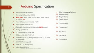
9. Arduino Specification
Microcontroller ATmega328
Operating Voltage 5V and 3.3 V
Baud Rate : 9600, 14400, 19200, 28800, 38400, 57600,
or 115200 bps.
Input Voltage (recommended) 7-12V
Input Voltage (limits) 6-20V
Digital I/O Pins 14 (of which 6 provide PWM output)
Analog Input Pins 6
DC Current per I/O Pin 40 mA
DC Current for 3.3V Pin50 mA
Flash Memory 32 KB (ATmega328) of which 0.5 KB used
by Bootloader
SRAM 2 KB (ATmega328)
EEPROM 1 KB (ATmega328)
Clock Speed 16 MHz
Other Prototyping Platform:
Raspberry pie
Beagle board
Panda board
Cotton candy
Cubie Board
APC Rock
Hackberry
Gooseberry
Prepared by- Md Asaduzzaman , Dept of ICT,MBSTU
9
10. Types of Arduino ?
Prepared by- Md Asaduzzaman , Dept of ICT,MBSTU
10
14. Types of Sensor
Two types:
1. Digital Sensor
2. Analog Sensor
Prepared by- Md Asaduzzaman , Dept of ICT,MBSTU
14
15. Frequently Used Sensor
Humidity sensor (DHT22) - Digital Sensor
Temperature sensor (LM35) - Analog Sensor
Water detector sensor (Simple Water Trigger) - Digital Sensor
PIR SENSOR - Digital Sensor
ULTRASONIC SENSOR - Digital Sensor
Sound Sensor - Digital Sensor
GPS
Prepared by- Md Asaduzzaman , Dept of ICT,MBSTU
15
16. Humidity Sensor (DHT22) –Digital Sensor
Technical Details
Power − 3-5V
Max Current − 2.5mA
Humidity − 0-100%, 2-5% accuracy
Temperature − 40 to 80°C, ±0.5°C accuracy
Prepared by- Md Asaduzzaman , Dept of ICT,MBSTU
16
17. Temperature Sensor (LM35) Analog Sensor
Technical Specifications:
Calibrated directly in Celsius (Centigrade)
Linear + 10-mV/°C scale factor.0.5°C ensured
accuracy (at 25°C)
Rated for full −55°C to 150°C range
Suitable for remote applications
Prepared by- Md Asaduzzaman , Dept of ICT,MBSTU
17
18. Water Sensor (Digital Sensor)
Technical Specification:
Water sensor has three terminals –
S,Vout(+), and GND (-).
Connect the sensor as follows −
Connect the +Vs to +5v on your Arduino
board.
Connect S to digital pin number 8 on Arduino
board.
Connect GND with GND on Arduino.
Prepared by- Md Asaduzzaman , Dept of ICT,MBSTU
18
19. PIR (Pyroelectric/Passive Infrared
Radiation) Sensor (Digital Sensor)
Technical Specification:
PIR sensor has three terminals : Vcc, OUT
and GND.
Connect the sensor as follows −
Connect the +Vcc to +5v on Arduino board.
Connect OUT to digital pin on Arduino
board.
Connect GND with GND on Arduino.
Prepared by- Md Asaduzzaman , Dept of ICT,MBSTU
19
20. Ultrasonic Sensor (HC-SR04) - Digital
Sensor
Technical Specifications
Power Supply − +5V DC
Quiescent Current − <2mA
Working Current − 15mA
Effectual Angle − <15°
Ranging Distance − 2cm – 400 cm/1″ – 13ft
Resolution − 0.3 cm
Measuring Angle − 30 degree
Connect the +5V pin to +5v on
your Arduino board.
Connect Trigger to digital pin 7 on
your Arduino board.
Connect Echo to digital pin 6 on
your Arduino board.
Connect GND with GND on
Arduino.Prepared by- Md Asaduzzaman , Dept of ICT,MBSTU
20
23. Types of Motor ??
There are three different type of motors −
DC motor
Servo motor
Stepper motor DC Motor
Servo motor
Stepper motor
Prepared by- Md Asaduzzaman , Dept of ICT,MBSTU
23
24. Necessary Things to done a Project with
Motor
Motor Driver : To control the direction of the spin of DC motor, without
interchanging the leads, you can use a circuit called an H-Bridge(Motor Driver).
An H-bridge is an electronic circuit that can drive the motor in both directions.
Example : L298, L293 ,ESC etc.
Prepared by- Md Asaduzzaman , Dept of ICT,MBSTU
24
L298 Motor Driver
25. Arduino Installation
First you must have your Arduino board and a USB cable.
Download Arduino IDE and driver.
IDE Link: ARDUINO 1.8.5 : https://www.arduino.cc/en/Main/Software
(go for windows installer) Download and Install it.
Driver Link: https://www.dropbox.com/s/a1d4837hbfylipb/windows-driver-
installer.exe?dl=0 Download and Install it.
Prepared by- Md Asaduzzaman , Dept of ICT,MBSTU
25
31. Upload a Sketch
A - used to check compile error.
B - Upload the program (Sketch).
C - Create new Sketch.
D - Open a Sketch.
E - Save a Sketch.
F – Serial monitor is Used to Visualize of transformation of serial data.
Prepared by- Md Asaduzzaman , Dept of ICT,MBSTU
31
38. Control Statement: Like as C/C++
If(condition) {…………}
If(condition) {………….} else {…………..}
If (condition) {…} else if (condition) {….} else {………}
switch (var) {
case 1:
//do something when var equals 1
break;
case 2:
//do something when var equals 2
break;
default:
// if nothing else matches, do the default
// default is optional
}
Prepared by- Md Asaduzzaman , Dept of ICT,MBSTU
38
39. Loop Statement: Like as C/C++
Do… while:
do
{
Statements;
break;
}
while(condition); // the statements are run at least once.
While:
While(condition)
{statements; break; }
for
for (int i=0; i <= val; i++){
statements;
break;
}
Prepared by- Md Asaduzzaman , Dept of ICT,MBSTU
39
40. Basic Structure of a Simple Project: 01
Blinking LED (Send a Digital Serial Write command to a Slave (Sensors,
LEDs, Motors etc.))
void setup() //the setup function runs once when you press reset or power the board.
{
pinMode(3, OUTPUT); // initialize digital pin 3 as an output.
}
void loop() // the loop function runs over and over again forever.
{
digitalWrite(3, HIGH); // turn the LED on (HIGH is the voltage level).
delay(1000); // wait for a second.
digitalWrite(3, LOW); // turn the LED off by making the voltage LOW.
delay(1000); // wait for a second.
}
Prepared by- Md Asaduzzaman , Dept of ICT,MBSTU
40
41. Circuit Diagram of Project: 01
Prepared by- Md Asaduzzaman , Dept of ICT,MBSTU
41
42. Basic Structure of a Simple Project: 02
Digital Serial Data Reading (Receive a command from a
Slave (Sensors, LEDs, Motors etc.))
int pushButton = 2; // digital pin 2 has a pushbutton attached to it. Give it a name:
void setup()
{
Serial.begin(9600); // initialize serial communication at 9600 bits per second:
pinMode(pushButton, INPUT); // make the pushbutton's pin an input:
}
void loop()
{
int buttonState = digitalRead(pushButton); // read the input pin:
Serial.println(buttonState); // print out the state of the button:
delay(1); // delay in between reads for stability
}
Prepared by- Md Asaduzzaman , Dept of ICT,MBSTU
42
43. Basic Structure of a Simple Project: 03
Analog Serial Data Reading (Receive a command from
a Slave ((Sensors, LEDs, Motors etc.))
void setup()
{
Serial.begin(9600); // initialize serial communication at 9600 bits per second:
}
void loop()
{
int sensorValue = analogRead(A0); // read the input on analog pin 0:
float voltage = sensorValue*(5.0/1023.0);
// Convert the analog reading(0-1023) to a voltage(0-5V):
Serial.println(voltage); // print out the value you read:
}
Prepared by- Md Asaduzzaman , Dept of ICT,MBSTU
43
44. Circuit diagram of Project- 03
Potentiometer
Prepared by- Md Asaduzzaman , Dept of ICT,MBSTU
44
45. Basic Structure of a Simple Project: 04
(Send a Analog Serial Write PWM command to a
Slave (Sensors, LEDs, Motors etc.))
void setup()
{
Serial.begin(9600); // initialize serial communication at 9600 bits per second:
}
void loop()
{
int Value = random(0,1023);
//set a analog serial data (which goes from 0 - 1023) to a voltage (0 - 5V):
float voltage = Value * (5.0 / 1023.0);
analogWrite(A1,voltage); // write the input on analog pin 1:
Serial.println(voltage); // print out the value you write:
}
Prepared by- Md Asaduzzaman , Dept of ICT,MBSTU
45
46. Can anyone tell us the Sketch
(code) of merging the idea of
Project -01,02,03 and Project -
04 ??
Prepared by- Md Asaduzzaman , Dept of ICT,MBSTU
46
47. Merge circuit Diagram of Project -03 and
Project -04
Prepared by- Md Asaduzzaman , Dept of ICT,MBSTU
47
48. Test Our Skills : (PWM) Anyone Please explain Where PWM is used?
int led = 3,brightness = 0,fadeAmount = 5;
void setup()
{
pinMode(led, OUTPUT);
}
void loop()
{
analogWrite(led, brightness);
brightness = brightness + fadeAmount;
if (brightness == 0 || brightness == 255)
{
fadeAmount = -fadeAmount ;
}
delay(30);
}
Prepared by- Md Asaduzzaman , Dept of ICT,MBSTU
48
49. Basic Project -05 Control the Spin of
Motor
const int pwm = 10 ;
const int in_1 = 9 ;
const int in_2 = 8 ;
void setup()
{
pinMode(pwm,OUTPUT) ;
pinMode(in_1,OUTPUT) ;
pinMode(in_2,OUTPUT) ;
}
void loop()
{
digitalWrite(in_1,HIGH) ;
digitalWrite(in_2,LOW) ;
analogWrite(pwm,255) ; //Clockwise for 3 secs
delay(3000) ;
digitalWrite(in_1,LOW) ;
digitalWrite(in_2,HIGH) ;
delay(3000) ; //Anti-Clockwise for 3 secs
}
Prepared by- Md Asaduzzaman , Dept of ICT,MBSTU
49
50. Basic Project -05 Control the Spin of
Motor Circuit diagram
Prepared by- Md Asaduzzaman , Dept of ICT,MBSTU
50
51. Project -06 : A Simple Home Security
System
Basic Idea : To build an human detection System for your Home using Arduino on
220v AC.
Instruments:
Arduino
PIR Sensor.
Relay Module (The relay board works on 220V AC .So keep necessary safety measurements.).
LED and Buzzer.
Motor.
Jumper Wire and Breadboard.
L298 Motor Driver.
Prepared by- Md Asaduzzaman , Dept of ICT,MBSTU
51
52. Project -06 :Smart home Security Circuit
Diagram
Prepared by- Md Asaduzzaman , Dept of ICT,MBSTU
52
53. Project-06: Sketch of Home Security
System
int LED = 3;
int PIR = 2;
int Buzzer = 7;
void setup()
{
pinMode(LED, OUTPUT);
pinMode(Buzzer, OUTPUT);
pinMode(PIR, INPUT);
}
Prepared by- Md Asaduzzaman , Dept of ICT,MBSTU
53
void loop() {
int value =
digitalRead(PIR);
if (value == HIGH){
digitalWrite(LED, HIGH);
digitalWrite(Buzzer,
HIGH);
}
else {
digitalWrite(LED, LOW);
digitalWrite(Buzzer,
LOW);
}
}
55. Video Tutorial of Building the Clap Control
Prepared by- Md Asaduzzaman , Dept of ICT,MBSTU
55
56. Project References
http://www.instructables.com/technology/arduino/ for project idea.
https://playground.arduino.cc/Projects/Ideas .
https://codebender.cc/home for project code Must need Firefox/chrome.
https://github.com for project code.
https://youtube.com for tutorial.
https://learn.sparkfun.com/tutorials for tutorial.
https://www.allaboutcircuits.com/projects/category/arduino/ for tutorial.
https://diyhacking.com/diy-projects/arduino-projects/ for project idea.
http://mertarduinotutorial.blogspot.com for tutorial.
Arduino for Dummies by- John Nussey.
Arduino Programming by- Simon Monk.
Prepared by- Md Asaduzzaman , Dept of ICT,MBSTU
56