SlideShare a Scribd company logo
3
Most read
6
Most read
7
Most read
MAHARAJA INSTITUTE OF TECHNOLOGY MYSORE
DEPARTMENT OF ELECTRONICS AND COMMUNICATION
TOPIC : NETWORK-LAYER PERFORMANCE
Presenting By :
Shashank M
4MH21EC085
NETWORK-LAYER PERFORMANCE
The collective network information to describe the quality of
services delivered by the underlying computer network is known
as "network performance". The network layer expect to receivean
ideal service, but the network layer is not perfect.
The performance of a networkcan be measured in terms of
1. Delay
2. Throughput
3. Packet Loss
4. Congestion Control (It is an issue that can improve the
performance)
1.Delay
All of us expect instantaneous response from a network, but a packet, from its source toits destination, encounters
delays. The delays in a network can be divided into four types:
1.Transmission Delay :A source host or a router cannot send a packet instantaneously. A sender needs to put the bits in
a packet on the line one by one. If the first bit of the packet is put on the lineat time t1 and the last bit is put on the line
at time t2, transmission delay of the packet is(t2 - t1). Definitely, the transmission delay is longer for a longer packet and
shorter if the sender can transmit faster.
Delaytr = (Packet length) / (Transmission rate).
2.Propagation Delay :Propagation delay is the time it takes for a bit to travel from point A to point B in the transmission
media. The propagation delay for a packet-switched network depends on the propagation delay of each network . The
propagation delay depends onthe propagation speed of the media, which is 3 X10⁸ meters/second in a vacuum and
normally much less in a wired medium; it also depends on the distance of the link.
Delaypg = (Distance) / (Propagation speed).
3.Processing Delay :The processing delay is the time required for a router or a destination host to receive a packet from
its input port, remove the header, perform an error detection procedure, anddeliver the packet to the output port or
deliver the packet to theupper-layer protocol . The processing delay may be different from each packet, but normally it is
calculated as an average.
Delaypr = Time required to process a packet in a router or a destination host
4.Queuing Delay :Queuing delay can normally happen in a router. A router has an input queue
connected to each of its input ports to store packets waiting tobe processed; the router also has an
output queue connected to each of its output ports to store packets waiting to be transmitted. The
queuing delay for a packet in a router ismeasured as the time a packet waits in the input queue
and output queue of a router.
Delayqu = The time a packet waits in input and output queues in a
router
Total Delay :Assuming equal delays for the sender, routers, and receiver, the total delay a
packet encounters can be calculated if we know the number of routers, n, in the whole path.
Total delay = (n + 1) (Delaytr + Delaypg + Delaypr) + (n) (Delayqu)
Note that if we have n routers, we have (n + 1) links. Therefore, we have (n + 1)
transmission delays related to n routers and the source, (n + 1) propagation delays related to (n +
1) links, (n + 1) processing delays related to n routers and the destination, and only n queuing
delays related to n routers.
2.Throughput
Throughput at any point in a network is defined as the number of bits passing through the point in a second,
which is actually the transmission rate of data at that point.
In a path from source to destination, a packet may pass through several links , each with a different
transmission rate. How, then, can we determine the throughput ofthe whole path to see the situation, assume
that we have three links, each with a different transmission rate, as shown in Figure.
In this figure, the data can flow at the rate of 200 kbps in Link1. However, when the data arrives at router
R1, it cannot pass at this rate. Data needs to be queued at the router and sent at 100 kbps. When data arrives
at router R2, it could be sent at the rate of 150 kbps, but there is not enough data to be sent. In other words,
the average rate ofthe data flow in Link3 is also 100 kbps. We can conclude that the average data rate for
this path is 100 kbps, the minimum of the three different data rates. The figure also shows that we can
simulate the behavior of each link with pipes of different sizes; the average throughput is determined by the
bottleneck, the pipe with the smallest diameter. In general, in a path with n links in series, we have
Throughput = minimum {TR1, TR2, . . . TRn}
3.Packet Loss
Another issue that severely affects the performance of communication is the number ofpackets lost
during transmission. When a router receives a packet while processing another packet, the received
packet needs to be stored in the input buffer waiting for itsturn. A router, however, has an input
buffer with a limited size. A time may come whenthe buffer is full and the next packet needs to be
dropped. The effect of packet loss on the Internet network layer is that the packet needs to be
resent, which in turn may createoverflow and cause more packet loss. A lot of theoretical studies
have been done in queuing theory to prevent the overflow of queues and prevent packet loss.
4.Congestion control
Congestion control is a mechanism for improving performance. Congestion at the network layer is
related to two issues, throughput and delay, which we discussed in the previous section.
A . When the load is much less than the capacity of the network, the delay is at a minimum. This
minimum delay is composed of propagation delay and processing delay, both of which are
negligible. However, when the load reaches the network capacity, thedelay increases sharply
because we now need to add the queuing delay to the total delay.
B . When the load is below the capacity of the network, the throughput increases proportionally
with the load. We expect the throughput to remain constant after the load reaches the capacity, but
instead the throughput declines sharply. The reason is the discarding of packets by the routers.
Computer Communication Networks, network layer performance.pptx

More Related Content

PPT
Chapter 7
PPT
Unit 3 Network Layer PPT
PPT
Chapter 4 - Digital Transmission
PPT
Osi , tcp/ip protocol and Addressing
PPTX
TCP and UDP
PPTX
Wlan wireless network
PPTX
Tcp header/IP Header/Authentication header
PPTX
Tcp IP Model
Chapter 7
Unit 3 Network Layer PPT
Chapter 4 - Digital Transmission
Osi , tcp/ip protocol and Addressing
TCP and UDP
Wlan wireless network
Tcp header/IP Header/Authentication header
Tcp IP Model

What's hot (20)

PDF
Data bit rate_by_abhishek_wadhwa
PPT
Chapter 20
PPT
Data link layer
PPTX
Twisted pair cable
PPT
Chapter 11
PPT
Topic : X.25, Frame relay and ATM
PPTX
Application layer
PPT
Guided Transmission Media
PPT
Network Layer,Computer Networks
PPT
osi vs tcp/ip
PPTX
Unit 2 data link control
PDF
Distributed deadlock
PPT
SYBSC IT COMPUTER NETWORKS UNIT III Wired LANS: Ethernet
PPT
chapter 11(Data link Control)in CN .ppt
PPT
Chapter 12
DOCX
Data link layer
PPTX
OSI Reference Model-Lecture-2.pptx
PPTX
switching techniques in data communication and networking
PPTX
Distance Vector Routing
PDF
Data bit rate_by_abhishek_wadhwa
Chapter 20
Data link layer
Twisted pair cable
Chapter 11
Topic : X.25, Frame relay and ATM
Application layer
Guided Transmission Media
Network Layer,Computer Networks
osi vs tcp/ip
Unit 2 data link control
Distributed deadlock
SYBSC IT COMPUTER NETWORKS UNIT III Wired LANS: Ethernet
chapter 11(Data link Control)in CN .ppt
Chapter 12
Data link layer
OSI Reference Model-Lecture-2.pptx
switching techniques in data communication and networking
Distance Vector Routing
Ad

Similar to Computer Communication Networks, network layer performance.pptx (20)

PPTX
CN UNIT III.pptx
PPT
UNIT-3 network security layers andits types
PPTX
Ch 18 intro to network layer - section 3
PPT
MODULE II.ppt
PDF
MODULE II.pdf
DOCX
network devices, types of delay
PDF
A throughput analysis of tcp in adhoc networks
PDF
A THROUGHPUT ANALYSIS OF TCP IN ADHOC NETWORKS
PDF
Ch1 delays, loss, and throughput l5
PDF
Computer Networks Module 2.pdf
PPTX
Mobile Transpot Layer
PPTX
Computer networks BTech 3rd year power point
PDF
CN R16 -UNIT-6.pdf
PPT
8 Packet Switching
PDF
PDF
Ba25315321
PDF
High performance communication networkss
PPTX
unit3-220228110900.pptx
DOCX
publication_6_17789_1425stream control transmission
PDF
CN UNIT III.pptx
UNIT-3 network security layers andits types
Ch 18 intro to network layer - section 3
MODULE II.ppt
MODULE II.pdf
network devices, types of delay
A throughput analysis of tcp in adhoc networks
A THROUGHPUT ANALYSIS OF TCP IN ADHOC NETWORKS
Ch1 delays, loss, and throughput l5
Computer Networks Module 2.pdf
Mobile Transpot Layer
Computer networks BTech 3rd year power point
CN R16 -UNIT-6.pdf
8 Packet Switching
Ba25315321
High performance communication networkss
unit3-220228110900.pptx
publication_6_17789_1425stream control transmission
Ad

More from Electro00 (14)

PPTX
information theory Digital Communication
PPTX
LSSD Level-Sensitive Scan Design VLSI ECE 6th Sem
PPTX
Semiconductor Memory Overview (Module 3)
PPTX
Wireless Network Generations (Optical and Wireless Communication)
PPTX
21EC72(OWC)Optical and wireless Communication
PPTX
QPSK(quadrature phase shift keying) Introduction
PPTX
Introduction-to-TCP (Transmission Control Protocol).pptx
PPTX
Introduction-to-the-World-Wide-Web(WWW).pptx
PPTX
Introduction-to-RIP(Routing Information Protocol).pptx
PPT
module11-ospf(Open Shortest Path First).ppt
PPTX
guava 1.pptx
PPTX
bambusa vulgaris 2nd ppt.pptx
PPTX
ashoka tree.pptx
PPTX
Acacia.pptx
information theory Digital Communication
LSSD Level-Sensitive Scan Design VLSI ECE 6th Sem
Semiconductor Memory Overview (Module 3)
Wireless Network Generations (Optical and Wireless Communication)
21EC72(OWC)Optical and wireless Communication
QPSK(quadrature phase shift keying) Introduction
Introduction-to-TCP (Transmission Control Protocol).pptx
Introduction-to-the-World-Wide-Web(WWW).pptx
Introduction-to-RIP(Routing Information Protocol).pptx
module11-ospf(Open Shortest Path First).ppt
guava 1.pptx
bambusa vulgaris 2nd ppt.pptx
ashoka tree.pptx
Acacia.pptx

Recently uploaded (20)

PDF
Exploratory_Data_Analysis_Fundamentals.pdf
PDF
A SYSTEMATIC REVIEW OF APPLICATIONS IN FRAUD DETECTION
PDF
Mitigating Risks through Effective Management for Enhancing Organizational Pe...
PPTX
Current and future trends in Computer Vision.pptx
PPT
A5_DistSysCh1.ppt_INTRODUCTION TO DISTRIBUTED SYSTEMS
PDF
keyrequirementskkkkkkkkkkkkkkkkkkkkkkkkkkkkkkkkkkkkk
PDF
PPT on Performance Review to get promotions
PPT
introduction to datamining and warehousing
PPTX
Safety Seminar civil to be ensured for safe working.
PDF
R24 SURVEYING LAB MANUAL for civil enggi
PDF
Level 2 – IBM Data and AI Fundamentals (1)_v1.1.PDF
PPTX
Artificial Intelligence
PPTX
communication and presentation skills 01
PDF
EXPLORING LEARNING ENGAGEMENT FACTORS INFLUENCING BEHAVIORAL, COGNITIVE, AND ...
PPTX
Information Storage and Retrieval Techniques Unit III
PDF
Abrasive, erosive and cavitation wear.pdf
PPTX
UNIT 4 Total Quality Management .pptx
PDF
Artificial Superintelligence (ASI) Alliance Vision Paper.pdf
PDF
The CXO Playbook 2025 – Future-Ready Strategies for C-Suite Leaders Cerebrai...
PPTX
Fundamentals of safety and accident prevention -final (1).pptx
Exploratory_Data_Analysis_Fundamentals.pdf
A SYSTEMATIC REVIEW OF APPLICATIONS IN FRAUD DETECTION
Mitigating Risks through Effective Management for Enhancing Organizational Pe...
Current and future trends in Computer Vision.pptx
A5_DistSysCh1.ppt_INTRODUCTION TO DISTRIBUTED SYSTEMS
keyrequirementskkkkkkkkkkkkkkkkkkkkkkkkkkkkkkkkkkkkk
PPT on Performance Review to get promotions
introduction to datamining and warehousing
Safety Seminar civil to be ensured for safe working.
R24 SURVEYING LAB MANUAL for civil enggi
Level 2 – IBM Data and AI Fundamentals (1)_v1.1.PDF
Artificial Intelligence
communication and presentation skills 01
EXPLORING LEARNING ENGAGEMENT FACTORS INFLUENCING BEHAVIORAL, COGNITIVE, AND ...
Information Storage and Retrieval Techniques Unit III
Abrasive, erosive and cavitation wear.pdf
UNIT 4 Total Quality Management .pptx
Artificial Superintelligence (ASI) Alliance Vision Paper.pdf
The CXO Playbook 2025 – Future-Ready Strategies for C-Suite Leaders Cerebrai...
Fundamentals of safety and accident prevention -final (1).pptx

Computer Communication Networks, network layer performance.pptx

  • 1. MAHARAJA INSTITUTE OF TECHNOLOGY MYSORE DEPARTMENT OF ELECTRONICS AND COMMUNICATION TOPIC : NETWORK-LAYER PERFORMANCE Presenting By : Shashank M 4MH21EC085
  • 2. NETWORK-LAYER PERFORMANCE The collective network information to describe the quality of services delivered by the underlying computer network is known as "network performance". The network layer expect to receivean ideal service, but the network layer is not perfect. The performance of a networkcan be measured in terms of 1. Delay 2. Throughput 3. Packet Loss 4. Congestion Control (It is an issue that can improve the performance)
  • 3. 1.Delay All of us expect instantaneous response from a network, but a packet, from its source toits destination, encounters delays. The delays in a network can be divided into four types: 1.Transmission Delay :A source host or a router cannot send a packet instantaneously. A sender needs to put the bits in a packet on the line one by one. If the first bit of the packet is put on the lineat time t1 and the last bit is put on the line at time t2, transmission delay of the packet is(t2 - t1). Definitely, the transmission delay is longer for a longer packet and shorter if the sender can transmit faster. Delaytr = (Packet length) / (Transmission rate). 2.Propagation Delay :Propagation delay is the time it takes for a bit to travel from point A to point B in the transmission media. The propagation delay for a packet-switched network depends on the propagation delay of each network . The propagation delay depends onthe propagation speed of the media, which is 3 X10⁸ meters/second in a vacuum and normally much less in a wired medium; it also depends on the distance of the link. Delaypg = (Distance) / (Propagation speed). 3.Processing Delay :The processing delay is the time required for a router or a destination host to receive a packet from its input port, remove the header, perform an error detection procedure, anddeliver the packet to the output port or deliver the packet to theupper-layer protocol . The processing delay may be different from each packet, but normally it is calculated as an average. Delaypr = Time required to process a packet in a router or a destination host
  • 4. 4.Queuing Delay :Queuing delay can normally happen in a router. A router has an input queue connected to each of its input ports to store packets waiting tobe processed; the router also has an output queue connected to each of its output ports to store packets waiting to be transmitted. The queuing delay for a packet in a router ismeasured as the time a packet waits in the input queue and output queue of a router. Delayqu = The time a packet waits in input and output queues in a router Total Delay :Assuming equal delays for the sender, routers, and receiver, the total delay a packet encounters can be calculated if we know the number of routers, n, in the whole path. Total delay = (n + 1) (Delaytr + Delaypg + Delaypr) + (n) (Delayqu) Note that if we have n routers, we have (n + 1) links. Therefore, we have (n + 1) transmission delays related to n routers and the source, (n + 1) propagation delays related to (n + 1) links, (n + 1) processing delays related to n routers and the destination, and only n queuing delays related to n routers.
  • 5. 2.Throughput Throughput at any point in a network is defined as the number of bits passing through the point in a second, which is actually the transmission rate of data at that point. In a path from source to destination, a packet may pass through several links , each with a different transmission rate. How, then, can we determine the throughput ofthe whole path to see the situation, assume that we have three links, each with a different transmission rate, as shown in Figure. In this figure, the data can flow at the rate of 200 kbps in Link1. However, when the data arrives at router R1, it cannot pass at this rate. Data needs to be queued at the router and sent at 100 kbps. When data arrives at router R2, it could be sent at the rate of 150 kbps, but there is not enough data to be sent. In other words, the average rate ofthe data flow in Link3 is also 100 kbps. We can conclude that the average data rate for this path is 100 kbps, the minimum of the three different data rates. The figure also shows that we can simulate the behavior of each link with pipes of different sizes; the average throughput is determined by the bottleneck, the pipe with the smallest diameter. In general, in a path with n links in series, we have Throughput = minimum {TR1, TR2, . . . TRn}
  • 6. 3.Packet Loss Another issue that severely affects the performance of communication is the number ofpackets lost during transmission. When a router receives a packet while processing another packet, the received packet needs to be stored in the input buffer waiting for itsturn. A router, however, has an input buffer with a limited size. A time may come whenthe buffer is full and the next packet needs to be dropped. The effect of packet loss on the Internet network layer is that the packet needs to be resent, which in turn may createoverflow and cause more packet loss. A lot of theoretical studies have been done in queuing theory to prevent the overflow of queues and prevent packet loss.
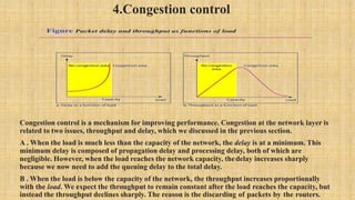
  • 7. 4.Congestion control Congestion control is a mechanism for improving performance. Congestion at the network layer is related to two issues, throughput and delay, which we discussed in the previous section. A . When the load is much less than the capacity of the network, the delay is at a minimum. This minimum delay is composed of propagation delay and processing delay, both of which are negligible. However, when the load reaches the network capacity, thedelay increases sharply because we now need to add the queuing delay to the total delay. B . When the load is below the capacity of the network, the throughput increases proportionally with the load. We expect the throughput to remain constant after the load reaches the capacity, but instead the throughput declines sharply. The reason is the discarding of packets by the routers.