Downloaded 272 times


The document outlines the techniques for analyzing material failures, including cleaning and microscopic examination of fracture surfaces to determine the cause of failure. It details various cleaning methods, such as dry air blast, chemical etching, and water-base detergent cleaning, along with the importance of fractography in understanding fracture modes and mechanical properties. The document highlights the role of chemical analysis and metallography in identifying compositional deviations and microstructural features that contribute to material failures.
Engr. Muhammad Ali Siddiqui introduces deformation behavior and failure analysis in materials.
Key laboratory techniques like cleaning, macro/microscopic examination, and mechanical testing for material failure analysis.
Techniques for cleaning fracture surfaces including air blast, organic solvents, and chemical etching.
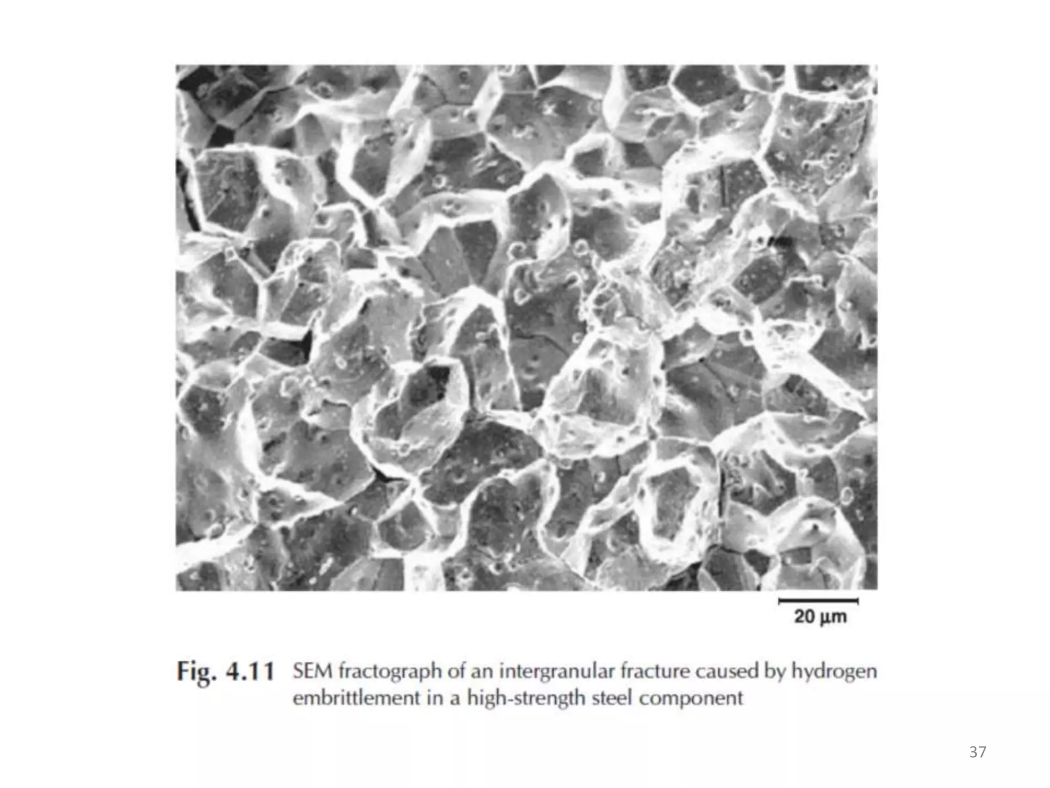
Fractography defined; techniques for both macrofractography and microfractography for analyzing fractures.
Steps for macroscopic fracture examination including type of fracture, origin, and physical features.Microscopic examination details, methods, and instruments to study fracture features and failure sources.
Chemical analysis methods for detecting deviations, impurities, and failure causes in materials.
Importance and methods for mechanical testing to ensure material strength and assess failure mechanisms.
Upcoming topics include Non-Destructive Testing Techniques and various modes of material failure.


