Downloaded 212 times


This document discusses key considerations for designing radiation shielding in diagnostic radiology facilities. It outlines parameters to calculate shielding needs such as workload, occupancy, equipment used, and dose constraints. Common materials for shielding like lead, concrete, and gypsum are mentioned. The importance of continuity of shielding and reducing penetrations is emphasized. Record keeping of shielding design is recommended.
Introduction to radiation protection in diagnostic and interventional radiology with focus on shielding and X-ray room design.
Overview of shielding theory, equipment design standards, safety requirements, and international guidelines.
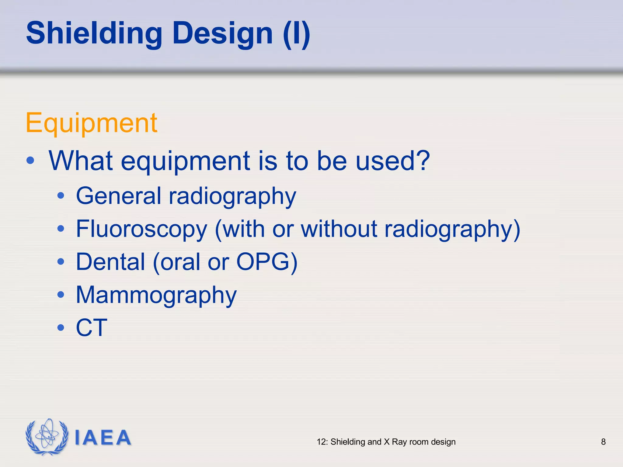
Shielding considerations including equipment types, usage patterns, and positioning of X-ray units.
Design layout and factors affecting shielding surrounding the X-ray room and derived shielding calculations.
Guidelines for using dose constraints, parameters, workload estimates, multi-tube considerations, and calculations.
Discusses materials for shielding construction and problems such as inadequate bonding and construction issues.
Addressing continuity in shielding, verification through measurements and visual checks, and importance of records.
Complexity of designing shielding and importance of standard assumptions and record-keeping for improvements.
References for additional information on radiation shielding and design standards for medical X-ray facilities.


