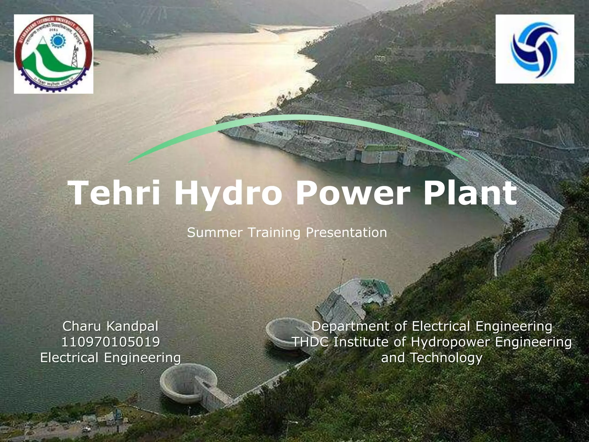
Tehri Hydro Power Plant
Summer Training Presentation
Charu Kandpal
110970105019
Electrical Engineering
Department of Electrical Engineering
THDC Institute of Hydropower Engineering
and Technology
16/12/2014
Contents
Introduction1
Power Generation2
Excitation System3
Braking System4
Gas Insulated Switchyard5
THDC IHET
Introduction
TEHRI HYDRO DEVELOPMENT CORPORATION, or
THDC, is a joint venture of the Central
Government and Uttar Pradesh State Government
(Now Uttarakhand Government).
The Tehri Dam is a multi-purpose rock and earth-
fill embankment dam at the confluence of
Bhagirathi and Bhilangna River at Tehri in
Uttarakhand, India. Tehri Hydro Power Projects
comprises of three phases.
THDC IHET16/12/2014
16/12/2014 THDC IHET
Phases of Tehri Hydro Plant
Phases
Phase 1 Phase 2 Phase 3
Tehri HEP
(4X250MW) was
completed in
2006.
Koteshwar HEP
(4X100MW) was
completed in 2012.
(4X250MW)
Pumped storage
Plant of
hydroelectricity
generation is
under
construction.
16/12/2014
Cycle Diagram
PSP
Storage HRT
Turbine
TRT
Water Flow
Diagram
Working of PSP
THDC IHET
Lower
Storage
16/12/2014 THDC IHET
Tehri HEP System Classification
Systems of
HEP
Generation System
Braking System
GIS System Tehri Excitation System
THDC IHET
Power Generation
Four Francis Turbines
Through BVC
Four Penstocks
Feeds Four
Turbines
Turbine Rotates Excited Rotor
Water Rotates Turbine Blades
One HRT = Two Penstocks
Water Flows Through HRTs
16/12/2014
According To Faraday’s Law
Pictorial Representation of
Generation
16/12/2014 THDC IHET
Need of an Excitation System
 The basic principle of power generation is when a
magnetic field is moved across a stationary conductor,
Voltage gets induced in the conductor.
 Voltage will be induced even if conductor is rotated and
magnetic field is kept stationary .
16/12/2014 THDC IHET
THDC IHET
Need of an Excitation System
1
Intensity of the
flux in rotating
magnetic field.
This can be
varied by DC
current
applying to the
electromagnet.
2 3
Length of the
conductor. This
can’t be varied
due to
manufacturing
reasons.
Generator output voltage is affected by the following factors:
Rate at which
flux lines cut
by the
conductor.
This can’t be
changed due
to the const.
speed
16/12/2014
THDC IHET
Braking System
Normal
Speed
1 2 3 4
Speed<50% Speed<4% END
16/12/2014
THDC IHET
Gas Insulated Switchyard
Power Grid Transmission
Generation
Transformer
GIS
Power Grid
Step Up 15.75 KV into
400 KV
Passed through GIS
Generation occurs at
15.75 KV
16/12/2014
Project report on THDC Hydrop Power Plant Summer Training

Project report on THDC Hydrop Power Plant Summer Training

  • 1.
    Tehri Hydro PowerPlant Summer Training Presentation Charu Kandpal 110970105019 Electrical Engineering Department of Electrical Engineering THDC Institute of Hydropower Engineering and Technology
  • 2.
  • 3.
    Introduction TEHRI HYDRO DEVELOPMENTCORPORATION, or THDC, is a joint venture of the Central Government and Uttar Pradesh State Government (Now Uttarakhand Government). The Tehri Dam is a multi-purpose rock and earth- fill embankment dam at the confluence of Bhagirathi and Bhilangna River at Tehri in Uttarakhand, India. Tehri Hydro Power Projects comprises of three phases. THDC IHET16/12/2014
  • 4.
    16/12/2014 THDC IHET Phasesof Tehri Hydro Plant Phases Phase 1 Phase 2 Phase 3 Tehri HEP (4X250MW) was completed in 2006. Koteshwar HEP (4X100MW) was completed in 2012. (4X250MW) Pumped storage Plant of hydroelectricity generation is under construction.
  • 5.
    16/12/2014 Cycle Diagram PSP Storage HRT Turbine TRT WaterFlow Diagram Working of PSP THDC IHET Lower Storage
  • 6.
    16/12/2014 THDC IHET TehriHEP System Classification Systems of HEP Generation System Braking System GIS System Tehri Excitation System
  • 7.
    THDC IHET Power Generation FourFrancis Turbines Through BVC Four Penstocks Feeds Four Turbines Turbine Rotates Excited Rotor Water Rotates Turbine Blades One HRT = Two Penstocks Water Flows Through HRTs 16/12/2014 According To Faraday’s Law
  • 8.
  • 9.
    Need of anExcitation System  The basic principle of power generation is when a magnetic field is moved across a stationary conductor, Voltage gets induced in the conductor.  Voltage will be induced even if conductor is rotated and magnetic field is kept stationary . 16/12/2014 THDC IHET
  • 10.
    THDC IHET Need ofan Excitation System 1 Intensity of the flux in rotating magnetic field. This can be varied by DC current applying to the electromagnet. 2 3 Length of the conductor. This can’t be varied due to manufacturing reasons. Generator output voltage is affected by the following factors: Rate at which flux lines cut by the conductor. This can’t be changed due to the const. speed 16/12/2014
  • 11.
    THDC IHET Braking System Normal Speed 12 3 4 Speed<50% Speed<4% END 16/12/2014
  • 12.
    THDC IHET Gas InsulatedSwitchyard Power Grid Transmission Generation Transformer GIS Power Grid Step Up 15.75 KV into 400 KV Passed through GIS Generation occurs at 15.75 KV 16/12/2014