Introduction to Geophysics Ali Oncel [email_address] Department of Earth Sciences KFUPM Seismic Exploration: Fundamentals 1
Nafe-Drake Curves suggesting that compressional wave velocity and density are directly proportional .   The below equation: Implies that P-wave velocity is inversely proportional to density, Explain the paradox. Homework, Due to Wednesday
Homework due to Wednesday Using the information in the below figures,  Explain the anomalous positions of Vp and Vs for ice.
Previous Lecture Elastic Coefficients and Seismic Waves Birc's Law Nafe-Drake Curve  Factors affecting P-wave and S-wave velocity  Seismic velocities for Geological Materials  Amplitude Changes of Particle Motions  Wavefronts and RayPaths  Seismic Trace  Seismic Wave Types
Reminder: Seismic Velocity in a homogeneous medium V=(appropriate elastic modulus/density) 1/2 What is relationship of rock density to seismic velocity? Inversely proportional to the square root of the density From Tom Boyd’s WWW Site - http://talus.mines.edu/fs_home/tboyd/GP311/introgp.shtml V  =     =  = k + (  )      + 2    p 4/3 V  =     =   s
Elastic Moduli Where    Shear Modules     Lame’s lambda constant E= Young’s module ρ= mass density σ =  Poisson’s ratio Bulk Module is k    =  k -  = 2    σ   E 3   ( 1 +  σ  ) ( 1 - 2  σ  ) k =  2    2  σ  υ
Reminder:  k  and   Bulk Modulus where      = dilatation  =   V/V  and  P  =  pressure =k=  (  P/  )  Ratio of increase in pressure to associated  volume change shear stress =  (  F /A)    = shear stress shear strain shear modulus shear strain =  (  l  /L) Force per unit area to change  the shape of the material
Reminder: Poisson’s Ratio Ratio Vp and Vs depends on Poisson ratio: where Poisson’s ratio varies from 0 to ½.  Poisson’s ratio has the value ½ for fluids
Reminder: Seismic Velocities (P-wave)
Rock Velocities (m/sec) pp. 18-19 of Berger
Reminder: Influences on Rock Velocities In situ versus lab measurements Frequency differences Confining pressure Microcracks Porosity Lithology Fluids – dry, wet Degree of compaction ……………
Huygen’s  Principle
Fermat’s Principle pp. 20 of Burger’s book.
Travel time graph .  The seismic traces are plotted according to the distance (X) from the source to each receiver.  The elapsed time after the source is fired is the travel time (T). Travel-Time Graph T=X/V X  distance from source to the receiver,   T   total time from the source to the receiver V   seismic velocity of the P, S, or R arrival. Initial wave fronts for   P, S and R waves , propagating across several receivers at increasing distance from the source.
Estimates of Seismic Velocity B) The slope of the travel time for each of the P,S, and R arrivals (see earlier figure) is the inverse of velocity. The slope of line for each arrival is the first derivative   ( dT/dX ).
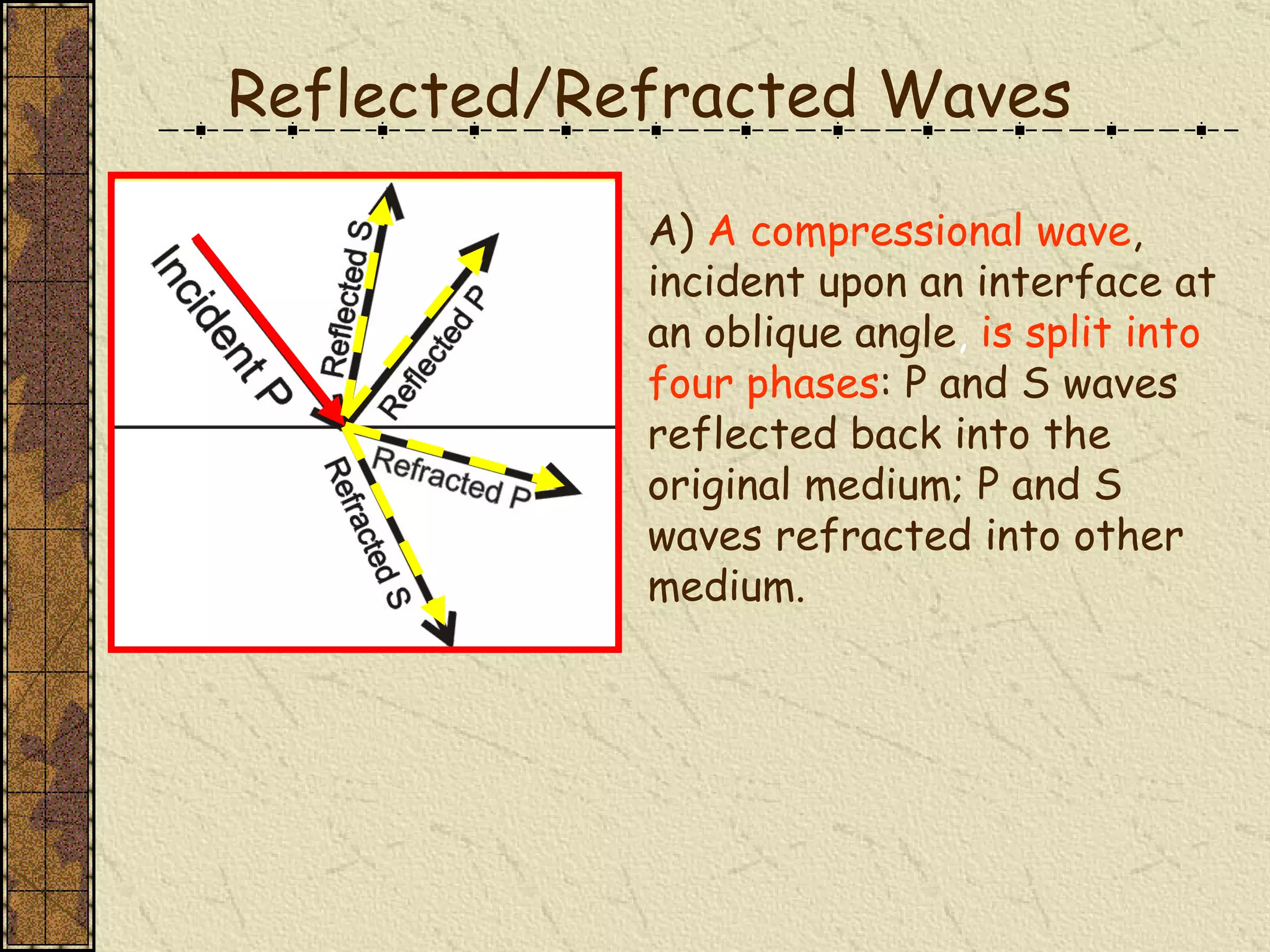
A)   A compressional wave , incident upon an interface at an   oblique   angle ,  is split into four phases : P and S waves reflected back into the original medium; P and S waves refracted into other medium. Reflected/Refracted Waves
Model Calculation Simple, Horizontal Two Layers Direct Wave?
Selected ray path (a) and travel-time curve  9b) for direct wave.  The slope, or first derivative, is the reciprocal of the velocity (V 1 ). Direct Wave
Model Calculation Simple, Horizontal Two Layers Reflected Wave?
Model Calculation Simple, Horizontal Two Layers Head Wave or Critically Refracted?
All Three Arrivals
Ray paths for direct, reflected, and critically refracted waves, arriving at receiver a distance   ( X )   from the source.  The interface separating velocity   ( V 1 )   from velocity   ( V 2 )   material is a distance   ( h )   below the surface. Ray paths
Snell’s Law- Critically Refracted Arrival For a wave traveling from material of velocity V 1  into velocity V 2  material, ray paths are refracted according to   Snell’s law . i 1  =   angle of incidence i 2 =   angle of refraction
Wave fronts are distorted from perfect spheres as energy transmitted into material of different velocity.  Ray paths thus   bend   (“ refract ”)   across an interface where   velocity changes .   The angles for incident and refracted are measured from a line drawn perpendicular to the interface between the two layers. Seismic Refraction
Behavior of Refracted Ray on Velocity Changes

ÖNCEL AKADEMİ: INTRODUCTION TO GEOPHYSICS

  • 1.
    Introduction to GeophysicsAli Oncel [email_address] Department of Earth Sciences KFUPM Seismic Exploration: Fundamentals 1
  • 2.
    Nafe-Drake Curves suggestingthat compressional wave velocity and density are directly proportional . The below equation: Implies that P-wave velocity is inversely proportional to density, Explain the paradox. Homework, Due to Wednesday
  • 3.
    Homework due toWednesday Using the information in the below figures, Explain the anomalous positions of Vp and Vs for ice.
  • 4.
    Previous Lecture ElasticCoefficients and Seismic Waves Birc's Law Nafe-Drake Curve Factors affecting P-wave and S-wave velocity Seismic velocities for Geological Materials Amplitude Changes of Particle Motions Wavefronts and RayPaths Seismic Trace Seismic Wave Types
  • 5.
    Reminder: Seismic Velocityin a homogeneous medium V=(appropriate elastic modulus/density) 1/2 What is relationship of rock density to seismic velocity? Inversely proportional to the square root of the density From Tom Boyd’s WWW Site - http://talus.mines.edu/fs_home/tboyd/GP311/introgp.shtml V =  = = k + ( )   + 2    p 4/3 V =  =   s
  • 6.
    Elastic Moduli Where  Shear Modules   Lame’s lambda constant E= Young’s module ρ= mass density σ = Poisson’s ratio Bulk Module is k  = k - = 2  σ E 3 ( 1 + σ ) ( 1 - 2 σ ) k = 2  2  σ υ
  • 7.
    Reminder: k and  Bulk Modulus where  = dilatation =  V/V and P = pressure =k= (  P/  ) Ratio of increase in pressure to associated volume change shear stress = (  F /A)  = shear stress shear strain shear modulus shear strain = (  l /L) Force per unit area to change the shape of the material
  • 8.
    Reminder: Poisson’s RatioRatio Vp and Vs depends on Poisson ratio: where Poisson’s ratio varies from 0 to ½. Poisson’s ratio has the value ½ for fluids
  • 9.
  • 10.
    Rock Velocities (m/sec)pp. 18-19 of Berger
  • 11.
    Reminder: Influences onRock Velocities In situ versus lab measurements Frequency differences Confining pressure Microcracks Porosity Lithology Fluids – dry, wet Degree of compaction ……………
  • 12.
  • 13.
    Fermat’s Principle pp.20 of Burger’s book.
  • 14.
    Travel time graph. The seismic traces are plotted according to the distance (X) from the source to each receiver. The elapsed time after the source is fired is the travel time (T). Travel-Time Graph T=X/V X distance from source to the receiver, T total time from the source to the receiver V seismic velocity of the P, S, or R arrival. Initial wave fronts for P, S and R waves , propagating across several receivers at increasing distance from the source.
  • 15.
    Estimates of SeismicVelocity B) The slope of the travel time for each of the P,S, and R arrivals (see earlier figure) is the inverse of velocity. The slope of line for each arrival is the first derivative ( dT/dX ).
  • 16.
    A) A compressional wave , incident upon an interface at an oblique angle , is split into four phases : P and S waves reflected back into the original medium; P and S waves refracted into other medium. Reflected/Refracted Waves
  • 17.
    Model Calculation Simple,Horizontal Two Layers Direct Wave?
  • 18.
    Selected ray path(a) and travel-time curve 9b) for direct wave. The slope, or first derivative, is the reciprocal of the velocity (V 1 ). Direct Wave
  • 19.
    Model Calculation Simple,Horizontal Two Layers Reflected Wave?
  • 20.
    Model Calculation Simple,Horizontal Two Layers Head Wave or Critically Refracted?
  • 21.
  • 22.
    Ray paths fordirect, reflected, and critically refracted waves, arriving at receiver a distance ( X ) from the source. The interface separating velocity ( V 1 ) from velocity ( V 2 ) material is a distance ( h ) below the surface. Ray paths
  • 23.
    Snell’s Law- CriticallyRefracted Arrival For a wave traveling from material of velocity V 1 into velocity V 2 material, ray paths are refracted according to Snell’s law . i 1 = angle of incidence i 2 = angle of refraction
  • 24.
    Wave fronts aredistorted from perfect spheres as energy transmitted into material of different velocity. Ray paths thus bend (“ refract ”) across an interface where velocity changes . The angles for incident and refracted are measured from a line drawn perpendicular to the interface between the two layers. Seismic Refraction
  • 25.
    Behavior of RefractedRay on Velocity Changes